Chapter 6 Control Modes of Operation ASDA-B2
6-6 Revision May, 2018
Pulse specification
Max.
input
frequency
Min. time width
T1 T2 T3 T4 T5 T6
High-
speed
pulse
Differential
Signal
4 Mpps 62.5ns 125ns 250ns 200ns 125ns 125ns
Low-
speed
pulse
Differential
Signal
500 Kpps 0.5μs 1μs 2μs 2μs 1μs 1μs
Open
collector
200 Kpps 1.25μs 2.5μs 5μs 5μs 2.5μs 2.5μs
Pulse specification
Max. input
frequency
Voltage
specification
Forward
specification
High-speed
pulse
Differential
Signal
4 Mpps 5V < 25 mA
Low-speed
pulse
Differential
Signal
500 Kpps 2.8V ~ 3.7V < 25 mA
Open collector 200 Kpps 24V (Max.) < 25 mA
The Source of External Pulse:
0: Low-speed optical coupler (CN1 Pin: PULSE, SIGN)
1: High-speed differential (CN1 Pin: HPULSE, HSIGN)
Position pulse can be input from these terminals, /PULSE (43), PULSE (41), HPULSE (38), /HPULSE (36),
/SIGN (39), SIGN (37) and HSIGN (42), /HSIGN (40). It can be an open-collector circuit or line driver.
Please refer to Chapter 3.10.1 for wiring method.
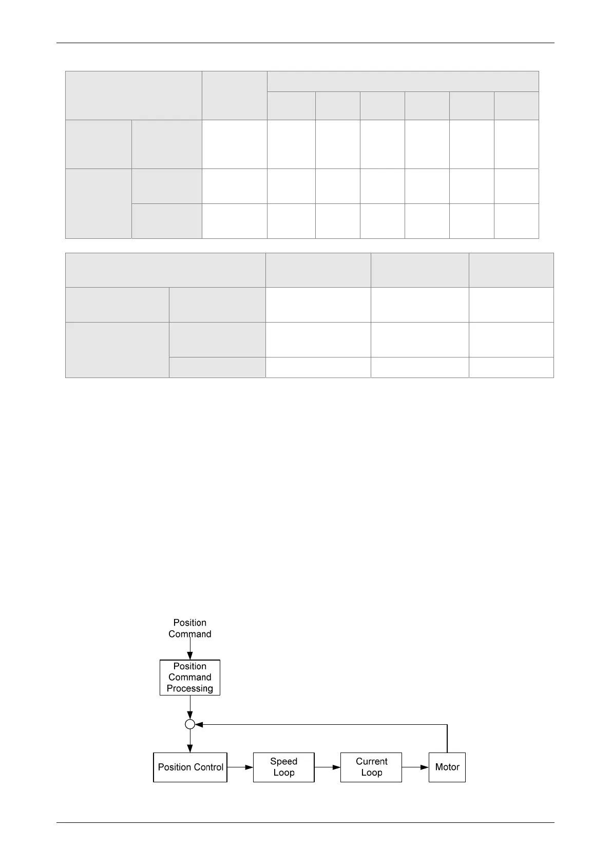
6.2.2 Control Structure of Position Mode
The basic control structure is as the following diagram:
 Loading...


