ASDA-B2 Chapter 3 Wiring
Revision May, 2018 3-17
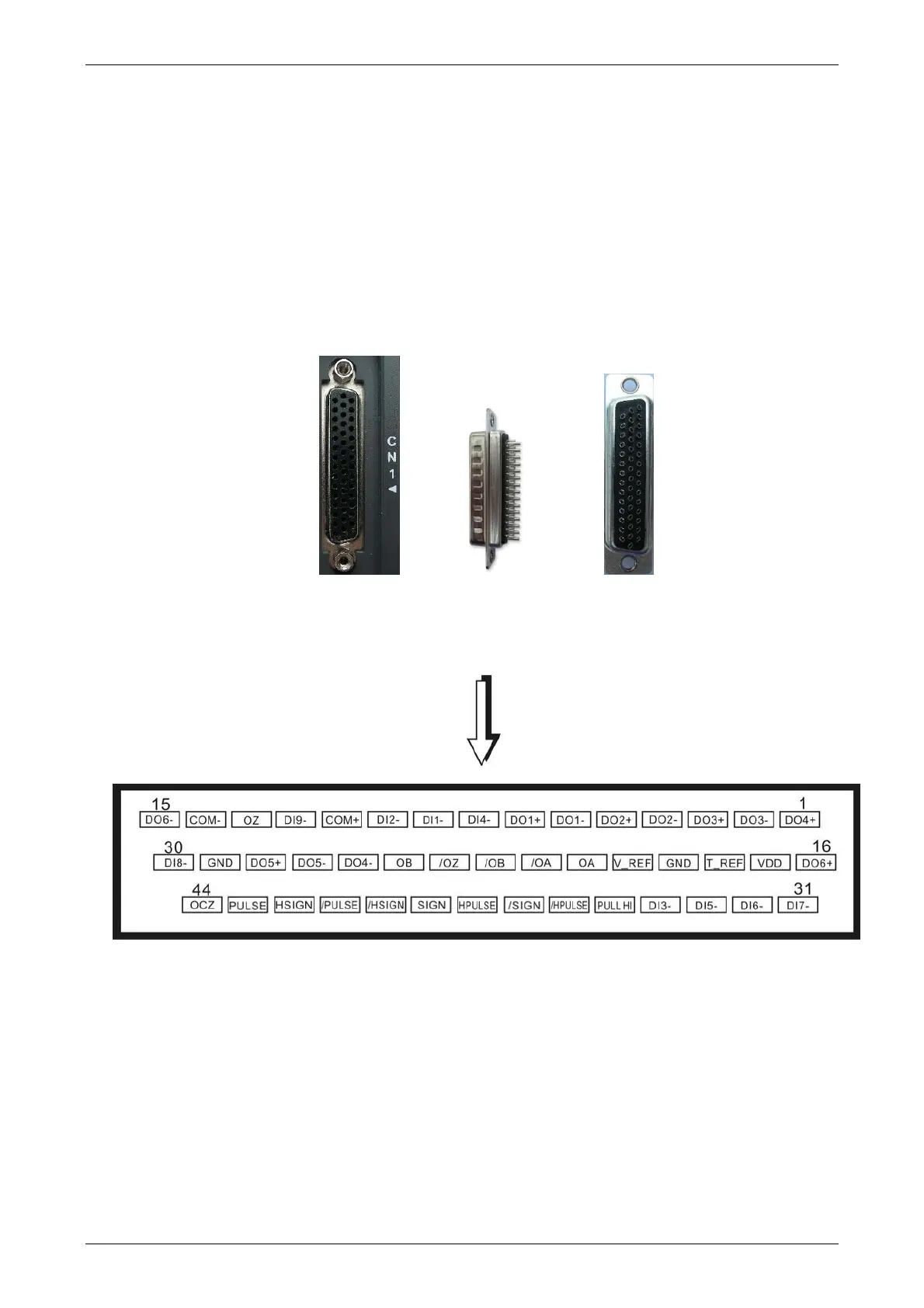
3.3 I / O Signal (CN1) Connection
3.3.1 I/O Signal (CN1) Connector Terminal Layout
In order to have a more flexible communication with the master, 6 programmable Digital
Outputs (DO) and 9 programmable Digital Inputs (DI) are provided. The setting of 9 digital
inputs and 6 digital outputs of each axis provided by ASDA-B2, which are parameter P2-
10~P2-17, P2-36 and parameter P2-18~P2-22, P2-37 respectively. In addition, the
differential output encoder signal, A+, A-, B+, B-, Z+ and Z-, input of analog torque
command, analog speed/position command and pulse position command are also
provided. The followings are the pin diagrams.
Side View Rear View

 Loading...


