Chapter 3 Wiring ASDA-B2
3-36 Revision May, 2018
The definition of each signal is as follows:
Drive Connector Encoder Connector
PIN No.
Terminal
Symbol
Description
Military
Connector
Quick
Connector
Color
4 T+
Serial communication
signal input / output (+)
A 1 Blue
5 T-
Serial communication
signal input / output (-)
B 4
Blue &
Black
8 +5V +5V power supply S 7
Red / Red
& White
7, 6 GND Ground R 8
Black /
Black &
White
Shell Shielding Shielding L 9 -
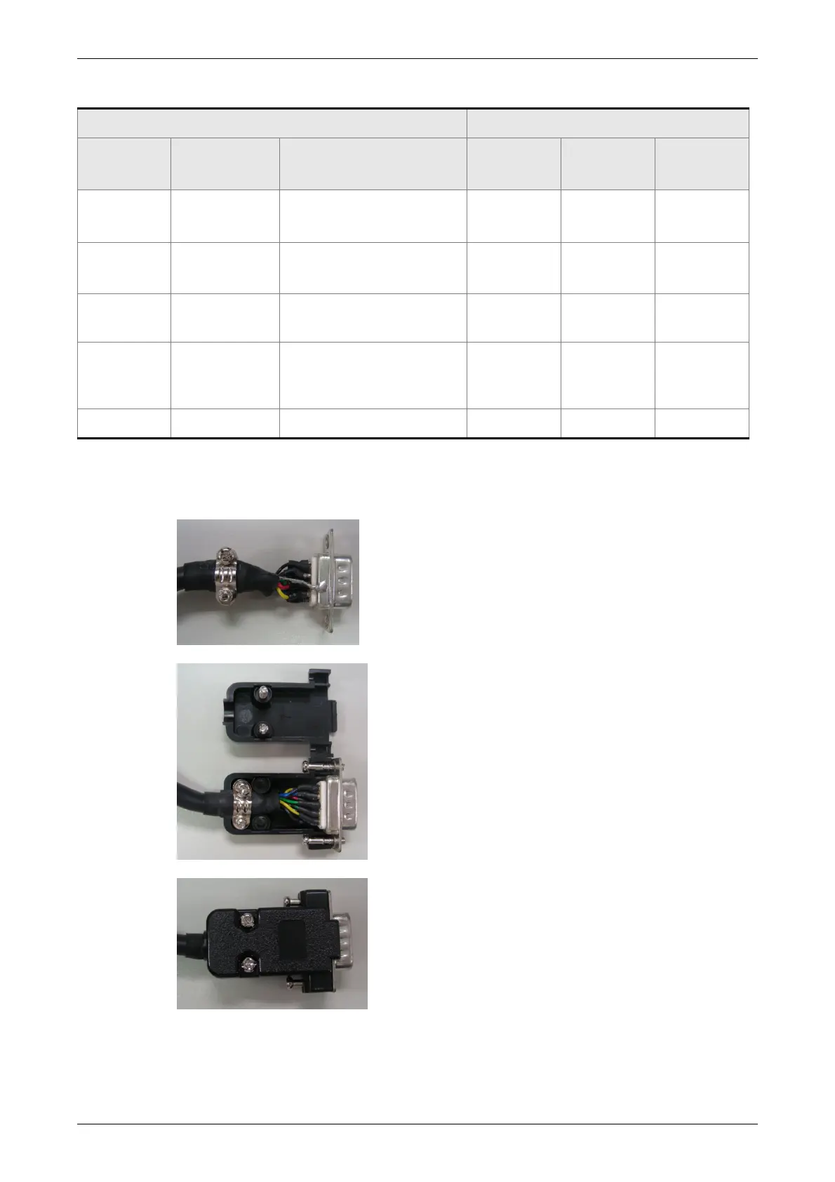
The shielding procedures of CN2 encoder connector are as followings:
(1) Solder the centre cores on the metal part of
the connector adequately for good ground
contact with the plate and shielding.
(2) Trim the ends of the cores and install the
cores with shielding into the plastic case of
the connector as shown in the figure.
(3) Tighten the screws to complete the
shielding.
 Loading...


