15
Installation and Operation Manual for Solar Power Inverter M70A EU V1.1 EN 2020-02-20
4 Product overview
AC-side components
Grid Alarm Explanation
Countdown (inverter is starting up).
The inverter is connected to the grid.
Error.
Power-o via external signal.
Warning.
Solar system failure.
Solar system warning.
No DC. Also appears when both DC isolat-
ing switches are open.
Updating rmware.
Standby mode.
Table 4.3.: Meaning of the LED displays on the inverter
4.4 AC-side components
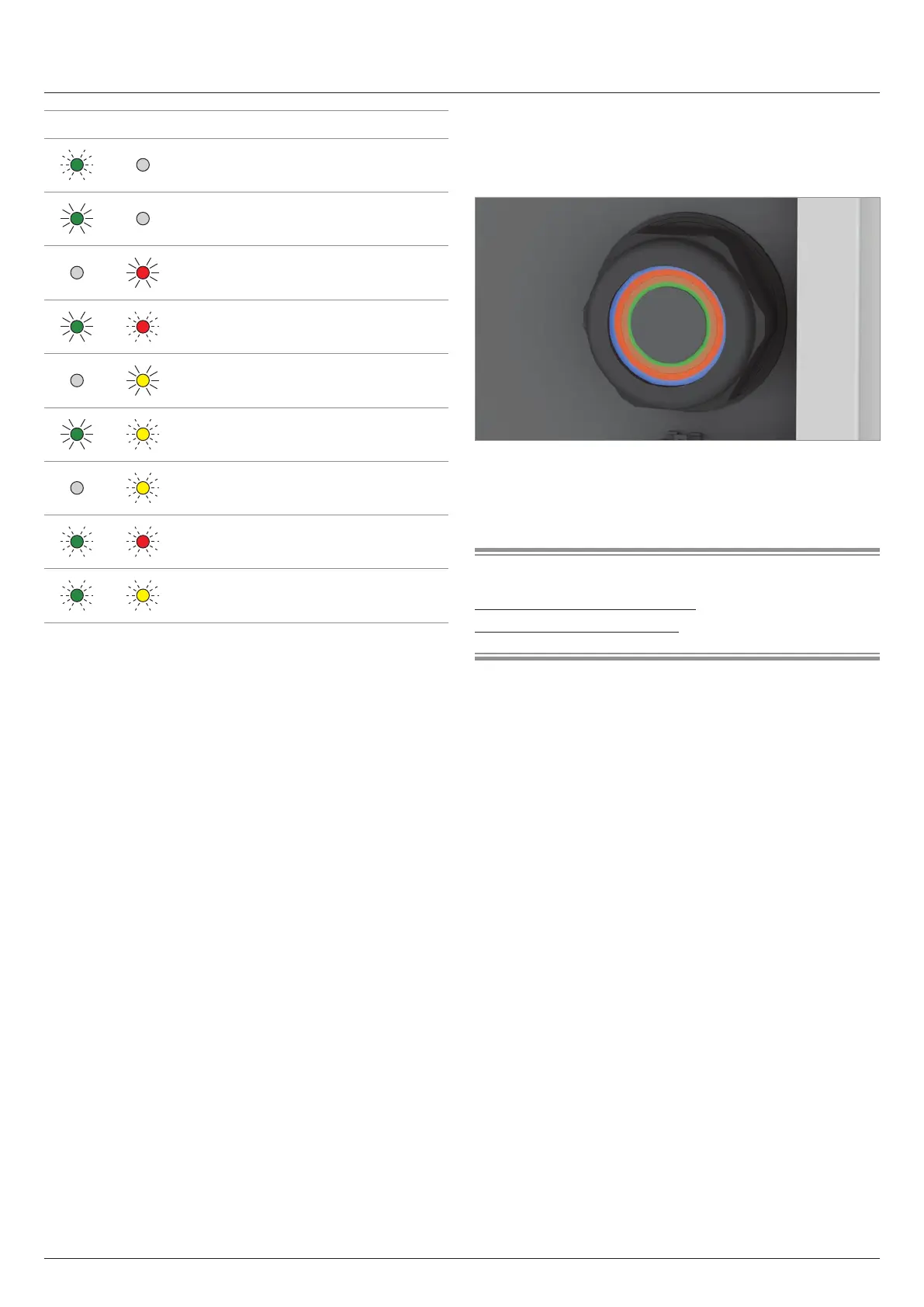
4.4.1 AC cable gland
Fig. 4.3: Position of the AC cable gland
The AC cable gland consists of several sealing rings for dierent
cable diameters.
Related topics
“5.4 Grid connection (AC)”, page 34
“7.10.3 AC cable gland”, page 85