21
Installation and Operation Manual for Solar Power Inverter M70A EU V1.1 EN 2020-02-20
4 Product overview
Cooling system
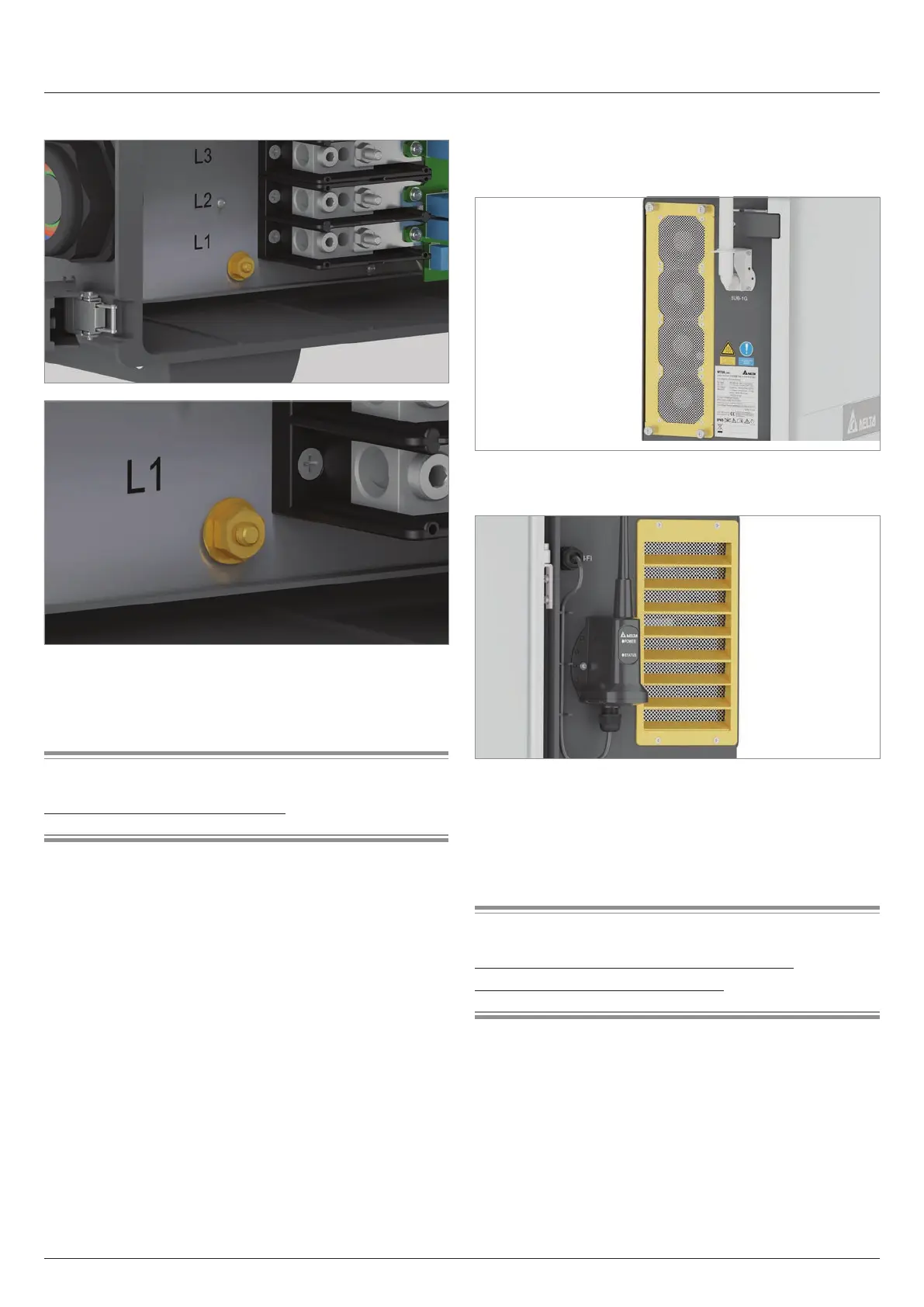
4.7.2 Internal PE connection
Fig. 4.15: Position of the internal PE connection
The M10 nut, spring washer and washer are already mounted in
the inverter. A toothed washer is not required.
Related topics
“5.4.6 Grounding the inverter”, page 35
4.8 Cooling system
4.8.1 Air inlet, air outlet and fan module
Fig. 4.16: Position of the air inlet with fan module on the left
side
Fig. 4.17: Position of the air outlet on the right side
The air for cooling is drawn in through the air inlet on the left side
of the inverter. The heated air is released back to the environ-
ment through the air outlets on the right side of the inverter.
The fan module can be replaced.
Related topics
“10.7 Cleaning/replacing the fan module”, page 121
“10.8 Cleaning the air outlets”, page 125