41
Installation and Operation Manual for Solar Power Inverter M70A EU V1.1 EN 2020-02-20
5 Planning the installation
Device communication and system monitoring
5.7 Device communication and system
monitoring
Related topics
“6. Planning the Commissioning”, page 48
“7.7 Connecting the communication card”, page 64
“7.8 Installing the Sub-1G antenna (optional)”, page 77
“7.9 Installing the Wi-Fi module before commissioning (optional)”,
page 80
5.7.1 Introduction
The inverter oers the following options for communication with
other devices (e.g. PC, smartphone, data logger):
● RS485 (communication card with RS485 connections,
digital inputs, dry contacts, external power-o and 12 V
DC
power supply)
● Sub-1G antenna (included in scope of delivery)
● Wi-Fi module (optional accessory)
5.7.2 Communication card
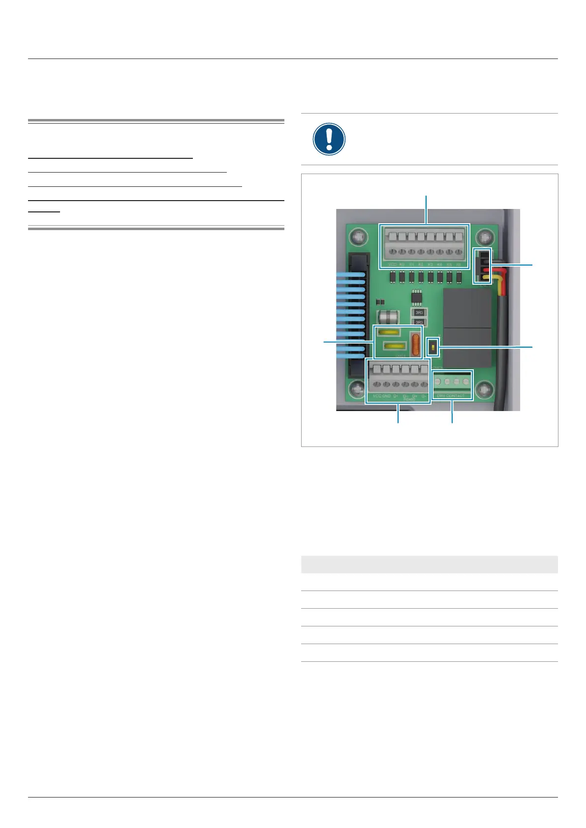
5.7.2.1 Components of the communication card
The connections for RS485, the digital inputs, the
dry contacts and the external power-o (EPO) are
all on the communication card. This means that
the installation work can be combined.
5 4
1
3
2
6
Fig. 5.35: Components of the communication card
1 Digital inputs and external power-o (terminal block)
2 Power supply for internal fan 1
3 DIP switch for RS485 termination resistor
4 2 x dry contacts (terminal block)
5 RS485 (terminal block)
6 Protection against electromagnetic interference (EMI)
Connection Connection type
2x RS485 (DATA+ and DATA–) Terminal block
1x VCC (12 V, 0.5 A) Terminal block
6x digital inputs Terminal block
2x dry contacts Terminal block
1x external power-o (EPO) Terminal block
Table 5.1.: Connections on the communication card