75
Installation and Operation Manual for Solar Power Inverter M70A EU V1.1 EN 2020-02-20
7 Installation
Connecting the communication card
7.7.5 Connecting a ripple control receiver
Pin Naming Short cir-
cuit
Assigned action
1 V1 - -
2 K0 V1 + K0 External power-o (EPO)
3 K1 V1 + K1
Maximum active power lim-
ited to 0 %
4 K2 V1 + K2
Maximum active power lim-
ited to 30 %
5 K3 V1 + K3
Maximum active power lim-
ited to 60 %
6 K4 V1 + K4
Maximum active power lim-
ited to 100 %
7 K5 V1 + K5 Reserved
8 K6 V1 + K6 Reserved
Table 7.3.: Pin assignment of the terminal block with digital inputs
for connecting a ripple control receiver
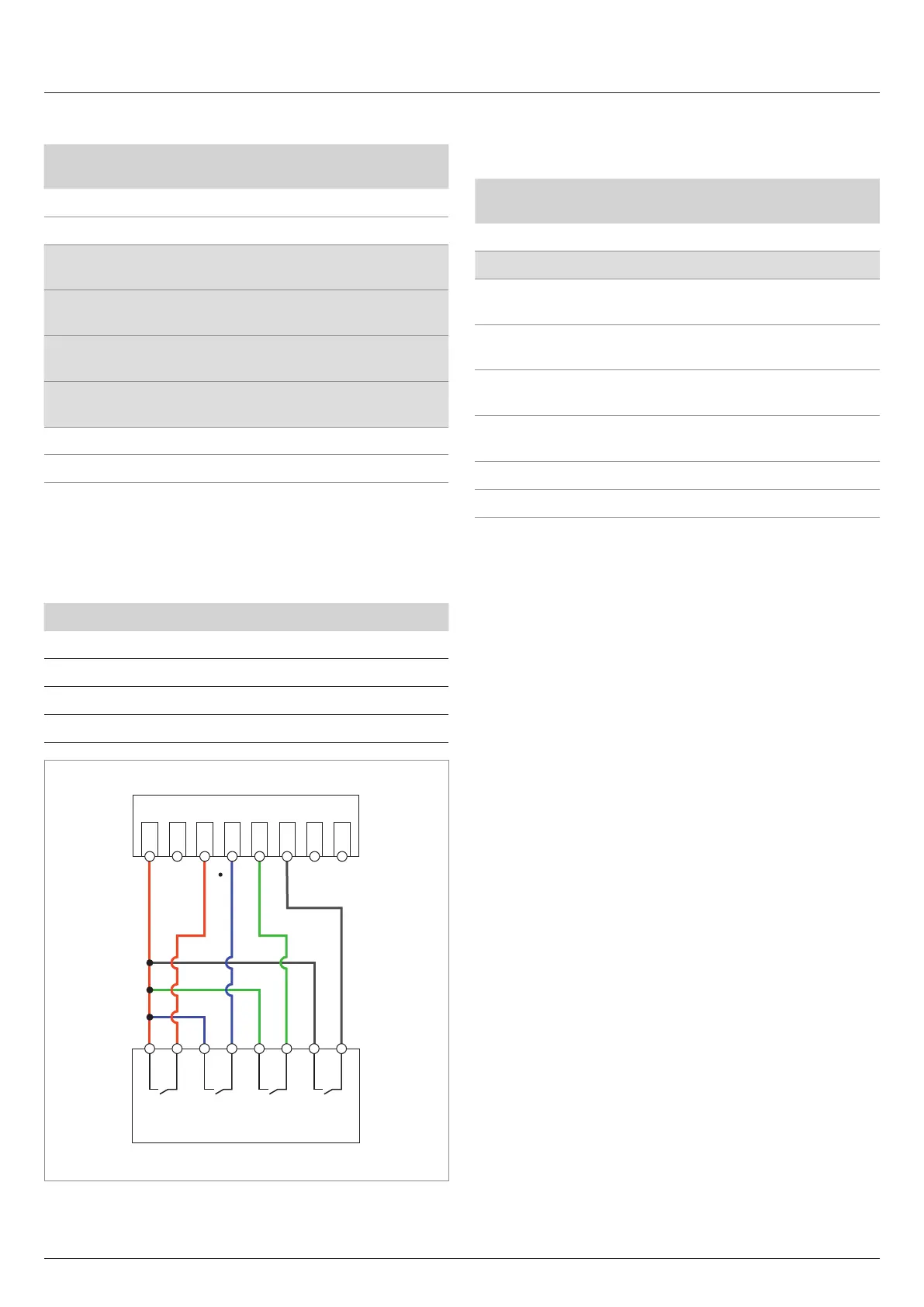
Connection schema
Power limiting to: Short circuit
0% Terminals V1 and K1
30% Terminals V1 and K2
60% Terminals V1 and K3
100% Terminals V1 and K4
R1 R2 R3 R4
V1 K0 K1 K2 K3 K4 K5 K6
Digital inputs
Ripple control receiver
Fig. 7.7: Connection diagram for a ripple control receiver
7.7.6 Connecting the external power-o (EPO)
Pin assignments
Pin Naming Short cir-
cuit
Assigned action
1 V1 - -
2 K0 V1 + K0 External power-o (EPO)
3 K1 V1 + K1
Maximum active power lim-
ited to 0%
4 K2 V1 + K2
Maximum active power lim-
ited to 30%
5 K3 V1 + K3
Maximum active power lim-
ited to 60%
6 K4 V1 + K4
Maximum active power lim-
ited to 100%
7 K5 V1 + K5 Reserved
8 K6 V1 + K6 Reserved
Table 7.4.: Pin assignment of the terminal block for the external
power-o
1. Connect the wires to the terminals V1 and K0.
2. After commissioning, the relay for the external power-o
can be dened with Delta Service Software as a normally
closed or normally open contact.