67
Installation and Operation Manual for Solar Power Inverter M70A EU V1.1 EN 2020-02-20
7 Installation
Connecting the communication card
7.7.3 Connecting a data logger via RS485
7.7.3.1 Introduction
NOTICE
Unwanted currents.
In some installation variants, unwanted currents
can ow when multiple inverters are connected
via RS485.
► Do not use GND and VCC.
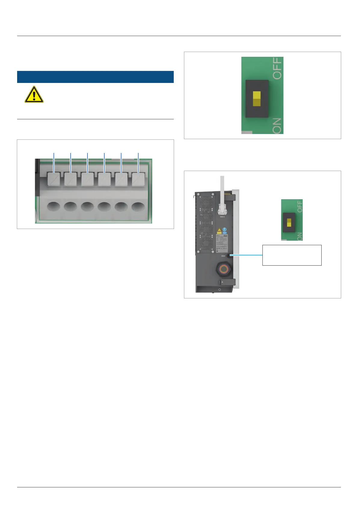
Terminal assignment of the RS485 terminal block
21 3 4 5 6
1 VCC (+12 V; 0.5 A)
2 GND
3 DATA+ (RS485)
4 DATA– (RS485)
5 DATA+ (RS485)
6 DATA– (RS485)
Fig. 7.38: Terminal assignment of the RS485 terminal block
Terminal pair 3/4 or 5/6 can be used to connect a data logger.
The second terminal pair is only required when connecting sev-
eral inverters via RS485. The second terminal pair can also be
used to connect a PC.
Data format
Baud rate 9600, 19200, 38400; Standard: 19200
Data bits 8
Stop bit 1
Parity Not applicable
DIP switch for the RS485 termination resistor
Fig. 7.1: DIP switch for the RS485 termination resistor
RS485 connection diagram for a single inverter
RS485
Termination resistor = ON
Data logger
Fig. 7.2: RS485 connection diagram for a single inverter