7 Installation
Connecting the communication card
Installation and Operation Manual for Solar Power Inverter M70A EU V1.1 EN 2020-02-20
68
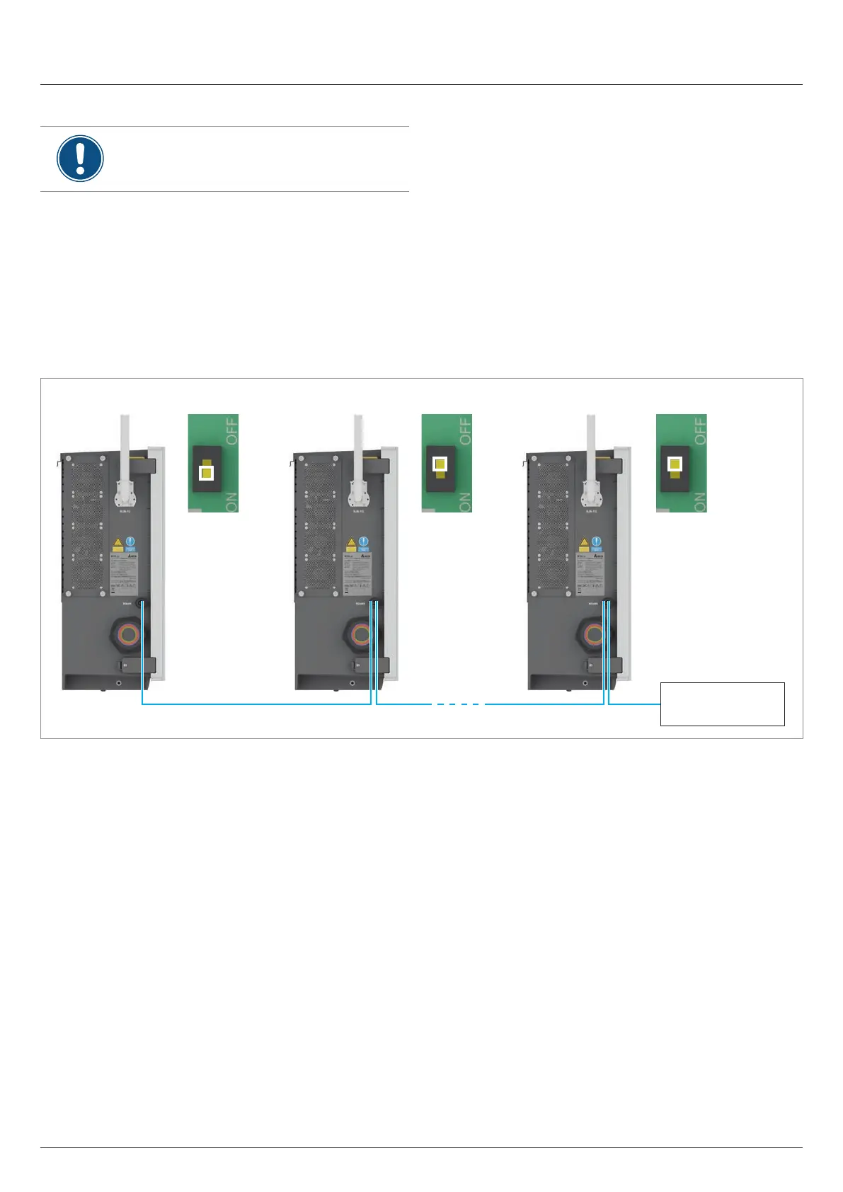
RS485 connection diagram for multiple inverters
If you are using a DC1 data collector from Delta,
also refer to the notes in the next section.
► On the last inverter in the RS485 series, set the DIP switch
of the RS485 termination resistor to ON.
► If the data logger is located at one end of the RS485 chain,
then also switch on the RS485 termination resistor of the
data logger. If the data logger does not have an integrated
RS485 termination resistor, then also switch on the DIP
switch of the rst inverter in the RS485 series, i.e. the one
that is directly connected to the data logger.
► Set a dierent inverter ID at each inverter during commis-
sioning of the inverters.
RS485
Termination resistor = OFF Termination resistor = OFFTermination resistor = ON
Data logger
Fig. 7.3: RS485 connection diagram for several inverters