5 Planning the installation
Grid connection (AC)
Installation and Operation Manual for Solar Power Inverter M70A EU V1.1 EN 2020-02-20
36
5.4.7 Requirements for the grid voltage
3P3W Voltage Range 3P4W Voltage Range
L1-L2 400 V
AC
-20%/+30% L1-N 230 V
AC
-20%/+30%
L1-L3 400 V
AC
-20%/+30% L2-N 230 V
AC
-20%/+30%
L2-L3 400 V
AC
-20%/+30% L3-N 230 V
AC
-20%/+30%
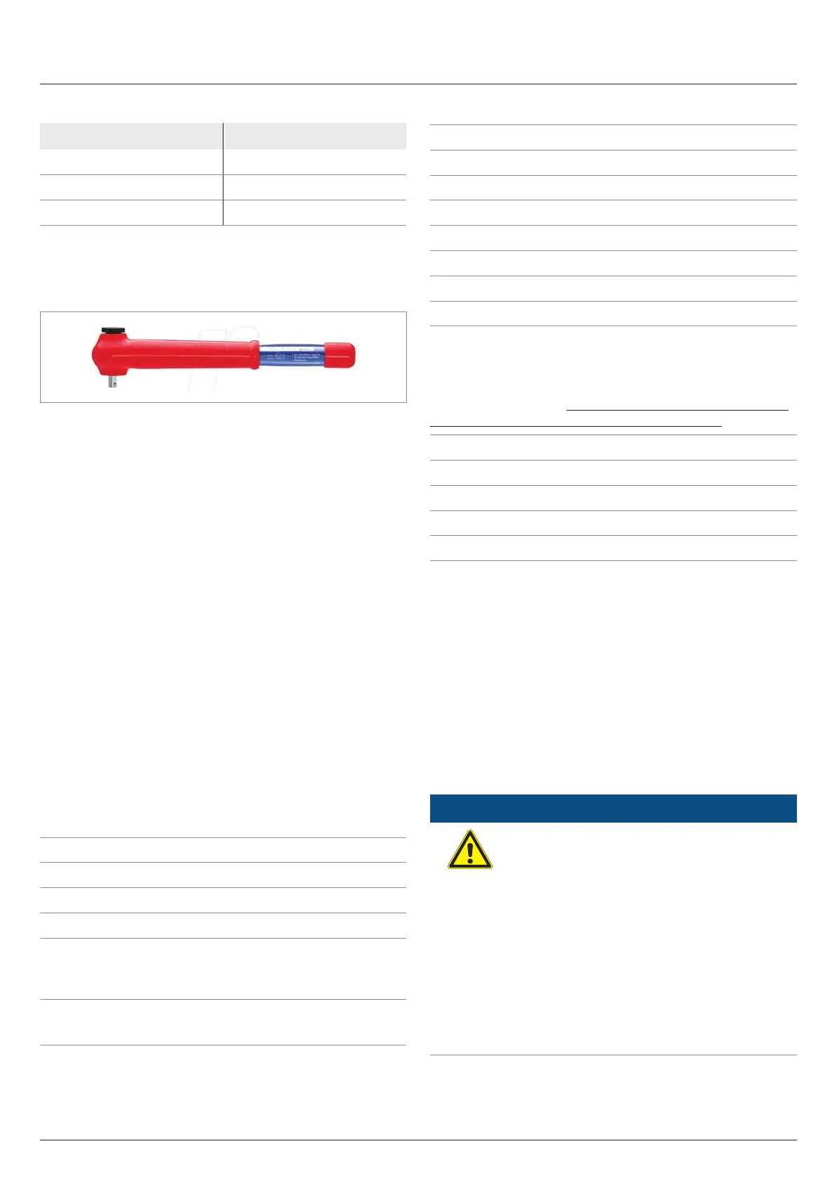
5.4.8 Special tools required
Use an insulated torque wrench.
5.4.9 Notes on calculating the cable cross-sec-
tion
Consider the following factors when calculating the cable
cross-section:
● Cable material
● Temperature conditions
● Cable length
● Installation type
● Voltage drop
● Loss of power in the cable
Always follow the IEC 60364-5-52 requirements and your coun-
try-specic installation instructions.
France: Follow the installation instructions of UTE 15-712-1. This
standard contains requirements for minimum cable cross-sec-
tions and to prevent overheating due to high currents.
Germany: Follow the installation instructions of VDE 0100-
712. This standard contains requirements for minimum cable
cross-sections and to prevent overheating due to high currents.
5.4.10 AC terminal block specications
Connection type Screws with hexagon socket head
Rated current I
N
96 A
Rated voltage U
N
1000 V
Attaching the conductor
Type of attachment
● 8 mm hexagon socket (L1,
L2, L3, N)
● M8 nut (PE)
Tightening torque
● 31 Nm (L1, L2, L3, N)
● 14, 7 Nm (PE)
5.4.11 Specication for copper cable
Min./max. Cable diameter 26.0 to 57.0 mm
Min./max. Wire cross-section
Without wire end sleeve
● Rigid cable 35–120 mm
2
● Multi-wire cable 35–120 mm
2
With wire end sleeve
● Flexible cable 35–120 mm
2
Stripping length 20 mm
5.4.12 Specication for aluminum cable
Aluminum cables can only be used in conjunction with Al-Cu
compression joints (see “5.4.14 Instructions regarding selection
and utilization of Al-Cu compression joints”, page 37)
Min./max. Cable diameter 26.0 to 57.0 mm
Min./max. Wire cross-section
Without wire end sleeve
● Rigid cable 35–120 mm
2
● Multi-wire cable 35–120 mm
2
5.4.13 Handling aluminum conductors during
installation work
The special properties of aluminum must be taken into consider-
ation when using aluminum:
● Aluminum "ows", i.e. it gives way under pressure.
● A thin non-conductive oxide layer forms within a few min-
utes on de-insulation, which increases the contact resis-
tance between the conductor and clamping point.
● The specic conductivity and hence the current carrying
capacity is approximately one third less than that of copper.
ATTENTION
To ensure a safe and reliable contact with alumi-
num conductors, always perform the following
work steps:
► Keep the installation location as free
as possible from moisture or corrosive
atmospheres.
► Connect the aluminum cables quickly.
► Clean the stripped end of the aluminum
conductor mechanically (for example,
using a knife blade to scrape o the oxide
layer), then immediately dip the aluminum
conductor into acid-fee and alkaline-free (=
neutral) Vaseline and straight away insert it
into the Al-Cu compression joint.