19
Installation and Operation Manual for Solar Power Inverter M70A EU V1.1 EN 2020-02-20
4 Product overview
Communication connection
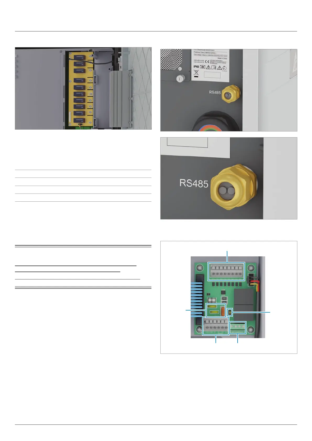
4.5.3 Type 2 DC surge protection devices
Fig. 4.11: Position of the type 2 DC surge protection devices
with the cover removed
The inverter has replaceable type-2 DC surge protection devices
which protect the inverter against excessive voltages. The type-2
DC surge protection devices are replaced as a block.
Type 2 OCM as per EN 50539-11
Current I
n
10 kA (8/20 µs)
Current I
max
20 kA (8/20 µs)
Voltage U
P
1,175 V
Table 4.5.: Specication of the pre-installed type-2 DC surge pro-
tection devices
Type 1+2 combined DC surge protection devices can be ordered
as accessories.
Related topics
“7.6 Installing the type 1+2 combined DC surge protection
devices before commissioning (optional)”, page 60
“10.9 Replacing the DC surge protection devices”, page 127
4.6 Communication connection
Fig. 4.12: Position of the cable gland for the communication
cables
4 3
1
2
5
Fig. 4.13: Components of the communication card
1 Digital inputs and external power-o (terminal block)
2 DIP switch for the RS485 termination resistor
3 2 x dry contacts (terminal block)
4 RS485 (terminal block)
5 Protection against electromagnetic interference (EMI)