4 Product overview
DC-side components
Installation and Operation Manual for Solar Power Inverter M70A EU V1.1 EN 2020-02-20
18
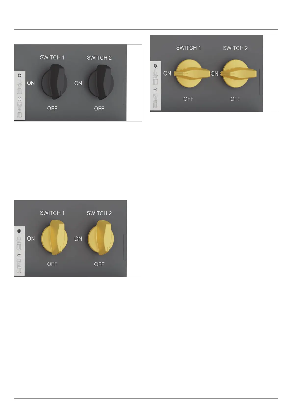
4.5.2 DC isolating switches
Fig. 4.8: Position of the two DC isolating switches
The DC isolating switches are marked on the inverter with
"SWITCH 1" and "SWITCH 2".
DC isolating switch 1 separates the DC strings of MPP trackers
1 to 3.
DC isolating switch 2 separates the DC strings of MPP trackers
4 to 6.
Germany: The DC isolating switches meet the requirements of
VDE 0100-712.
France: The DC isolating switches meet the requirements of
UTE 15-712-1.
Fig. 4.9: Both DC isolating switches in the OFF position = the
connection to the solar modules is disconnected
The connection between the inverter and the solar modules
isdisconnected when both DC isolating switches are in the OFF
position.
Fig. 4.10: Both DC isolating switches in the ON position = the
connection to the solar modules is closed
The connection between the inverter and the solar modules
isclosed when both DC isolating switches are in the ON position.