27
Installation and Operation Manual for Solar Power Inverter M70A EU V1.1 EN 2020-02-20
5 Planning the installation
Installation location
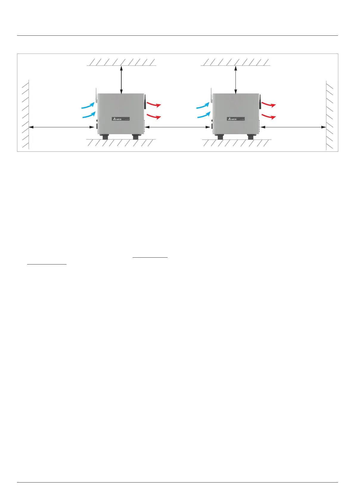
5.1.5 Installation clearances
>30 cm >60 cm >30 cm
>20 cm
>20 cm
and air circulation
Fig. 5.24: Installation clearances and air circulation
► Observe the minimum bend radius of the cables used (es-
pecially the AC cable)!
► Ensure the accessibility of the side components (air lters,
fan module, AC cable gland, DC connector panel, etc.) for
maintenance and repair work.
► Allow space to the front to open the door.
► Ensure sucient air circulation. There must not be heat
buildup around the inverter.
► Position multiple inverters so that they do not heat each
other up.
► Observe Operating temperature range without derating
the Total operating temperature range (see “11. Technical
Data”, page 144). When the Operating temperature range
without derating is exceeded, the inverter reduces the AC
power fed into the grid. When the Total operating tempera-
ture range is exceeded, the inverter stops feeding AC pow-
er into the grid. This is normal operating behavior for the
inverter and is necessary to protect the internal electronics.
► In areas with many trees or elds, plant parts can clog the
air lters and obstruct the air ow.