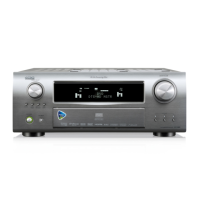
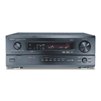
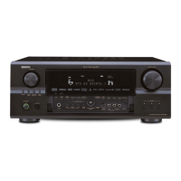
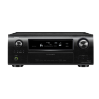
7
AVR-3808CI / AVR-3808 / AVC-3808
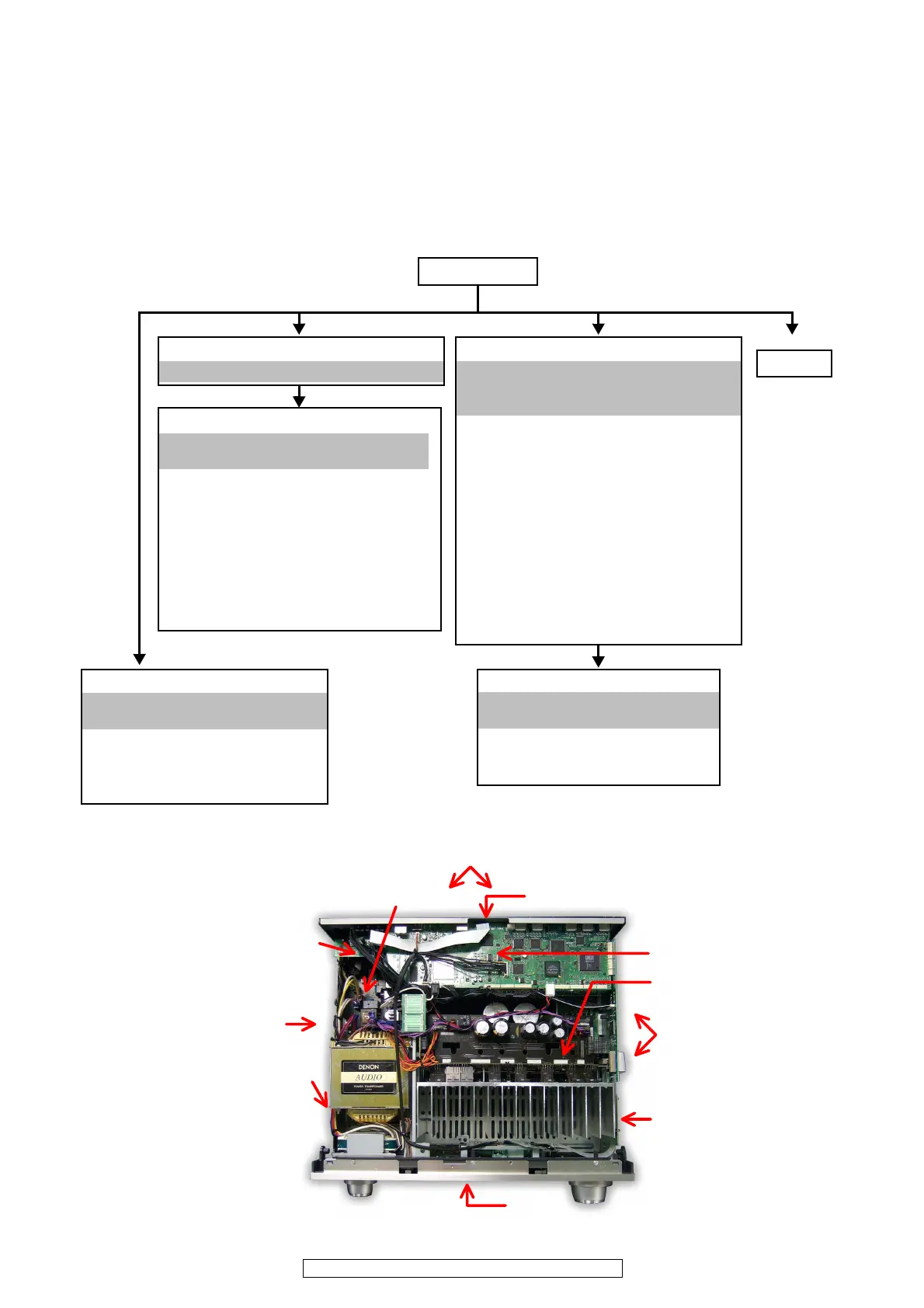
DISASSEMBLY
• Disassemble in order of the arrow of the figure of following flow.
下記フロー図の矢印の順番にはずしてください。
• In the case of the re-assembling, assemble it in order of the reverse of the following flow.
再組み立ての場合は、下記のフローの逆の順番に組立ててください
• In the case of the re-assembling, observe "attention of assembling" it.
再組み立ての場合は、「組立のご注意」を遵守してください。
Front panel sub ass’y
Refer to "EXPLODED VIEWS(2/3)"
(FRONT PANEL UNIT)
• 2-3 : FRONT UNIT
• 2-4 : MIC UNIT
• 2-5 : USB UNIT
• 5-2 : FLD UNIT
• 5-3 : FUNC UNIT
• 5-4 : H/P UNIT
• 5-5 : P.SW UNIT
• 5-7 : FUNC CONNECT UNIT
• 5-8 : H/P CONNECT UNIT
Top cover
Front panel
Refer to "
DISASSEMBLY 1.Front panel
unit"
Back panel
Refer to "
DISASSEMBLY 2.Back panel unit
"
and
"EXPLODED VIEWS(3/3)"
(BACK PANEL UNIT)
• 1 : DIGITAL UNIT
• 2-1 : A.VIDEO UNIT
• 2-2 : VIDEO CONNECT UNIT
• 2-6 : DIGITAL IN UNIT
• 2-7 : 232C UNIT
• 3-2 : IPOD UNIT
• 3-3 : AUDIO CONNECT UNIT
• 4-2 : P.SUPPLY1 UNIT
• 3-4 : LR CONNECT UNIT
• 4-4 : SIDE CONNECT UNIT
• 5-6 : TOP CONNECT UNIT
• 6-1 : AUDIO UNIT
• 6-2 : MAIN CPU UNIT
Radiator unit
Refer to "EXPLODED VIEWS(3/3)"
(RADIATOR UNIT)
• 3-1 : P.AMP UNIT
• 4-3 : VOL_AMP UNIT
• 5-1 : P.SUPPLY UNIT
Trans
Power unit
Refer to "EXPLODED VIEWS(1/3)"
(MAIN UNIT)
• 4-1 : PRIMARY UNIT
• 4-2 : P.SUPPLY1 UNIT
• 5-6 : TOP CONNECT UNIT
• 7 : DIGITAL POWER UNIT ASSY
【
Picture C
】
【
Picture D
】
【
Picture K,L
】
【
Picture G
】
【
Picture B
】
【
Picture E
】
【
Picture A
】
【
Picture F
】
【
Picture H
】
【
Picture I
】
【
Picture J,M
】
The viewpoint of each photograph
(photography direction)
各図の視点(撮影方向)
 Loading...