16
Port Assignment, Termination, Cable Lengths Installation
Port Assignment, Termination,
Cable Lengths
S
0
Ports
Whether you use the switchable
S
0
ports for internal or external com-
munication depends on your com-
munications requirements and the
existing basic accesses.
Please note that the S
0
bus requires
a terminating resistor. Resistors in
the OpenCom 100 and OpenCom
120 are marked with an R in the
diagram Positions of the Ports on
page 15, and are realised as gravity
hooks. Open the switch if you do not
wish to terminate the bus with the
OpenCom 100 but at its ends.
In the case of the OpenCom 105, the
S
0
buses are terminated by software.
You make this setting in the S
0
port
configuration in the Configurator
on the Web console.
You can connect up to eight termi-
nals on every internal S
0
bus; up to
three of the terminals can operate
without an external power supply.
The length of the four-wire cable of
an internal S
0
bus must not exceed
150 m. The power consumption of
each internal S
0
bus is approx. 3 W.
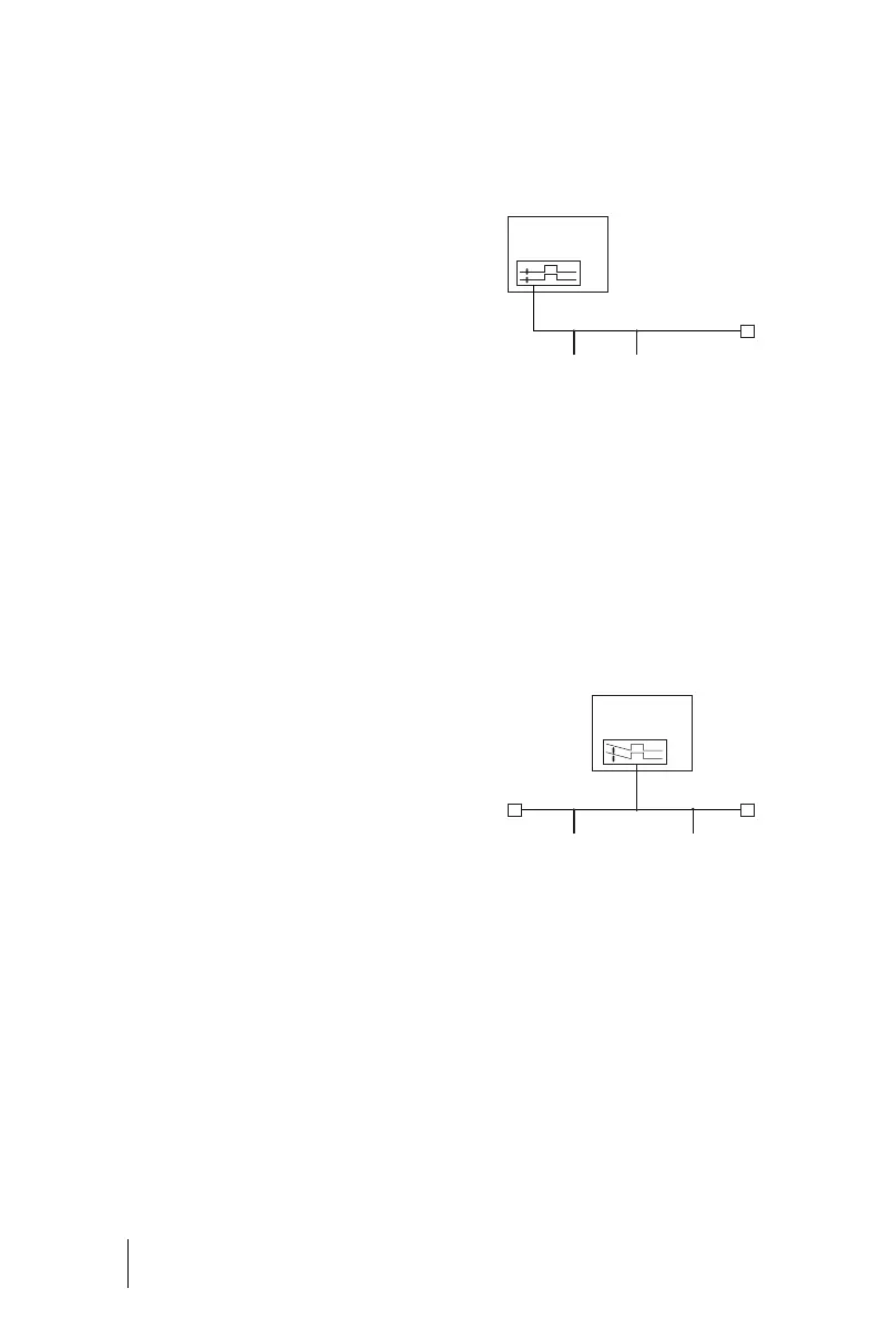
The S
0
bus is terminated at one end by
the OpenCom 100; the gravity hook is
closed.
IAE=ISDN connection unit (“ISDN
socket”) or an ISDN device.
TR= terminal resistor, the S
0
terminat-
ing resistor. The TR must be at the ter-
mination of the line. This can also be
done by means of a correspondingly
switched IAE.
The S
0
bus is terminated by means of
the TR at the ends: the gravity hook is
open.
U
pn
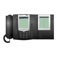
Ports
The U
pn
ports enable the connection
of one DECT base station each, or an
OpenPhone 61, 63 or 65, by means
of a twin-wire cable.
OpenCom 110
OpenCom 120
R
IAE IAE
TR
OpenCom 110
OpenCom 120
R
IAE
TRTR
IAE