16. Power supply trouble Field Service Ver. 1.0 Apr. 2005
152
ineo 161
ineo 210
Troubleshooting
16. Power supply trouble
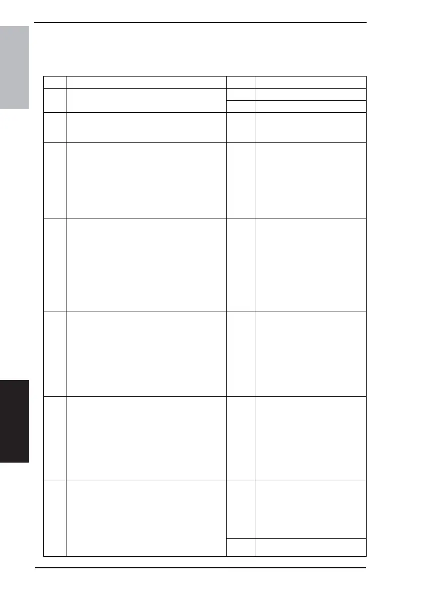
16.1 The copier does not turn ON
Step Check Result Action
1
A malfunction code appears when the Power
Switch is turned ON.
YES • Go to step 2.
NO • Go to step 3.
2
The malfunction is temporarily reset when the
Power Switch is turned OFF and ON with the Stop
key held down.
YES
• Perform the troubleshooting
procedure according to the mal-
function code.
3
Power supply voltage check
<Check Procedure>
Check voltage across pins of DC Power Supply
(PU1) when the Power Switch is turned ON.
• Voltage across CN1PU1-1 and CN1PU1-2
AC0 V when the Power Switch is OFF
Rated AC voltage when the Power Switch is
turned ON
NO
• Check wall outlet for voltage.
• Check power cord for continuity.
• Check Power Switch.
4
Check of output of DC24 V to Control Board
(copier: PWB-C)
<Check Procedure>
Check voltage across a Control Board (copier:
PWB-C) pin and GND when the Power Switch is
turned ON.
• Voltage across P110C/C-1 and GND
• Voltage across P110C/C-2 and GND
DC0 V when the Power Switch is OFF
DC24 V when the Power Switch is turned ON
NO
• Check Front Door Interlock
Switch (S3).
• Check Right Door Interlock
Switch (S4).
• Change DC power Supply
(PU1).
5
Check of output of DC24 V to Master Board
(copier: PWB-A)
<Check Procedure>
Check voltage across a Master Board (copier:
PWB-A) pin and GND when the Power Switch is
turned ON.
• Voltage across PJ2A-2 and GND
DC0 V when the Power Switch is OFF
DC24 V when the Power Switch is turned ON
NO
• Check Front Door Interlock
Switch (S3).
• Check Right Door Interlock
Switch (S4).
• Change DC power Supply
(PU1).
6
Check of output of DC 5 V to Master Board
(copier: PWB-A)
<Check Procedure>
Check voltage across a Master Board (copier:
PWB-A) pin and GND when the Power Switch is
turned ON.
• Voltage across PJ6A-9 and GND
DC0 V when the Power Switch is OFF
DC24 V when the Power Switch is turned ON
NO
• Change DC power Supply
(PU1).
7
Check of output of DC5 V to control panel (UN2)
<Check Procedure>
Check voltage across a Control Board (copier:
PWB-C) pin and GND when the Power Switch is
turned ON.
• Voltage across P102C/C-1 and GND
DC0 V when the Power Switch is OFF
DC5 V when the Power Switch is turned ON
NO
• Check Control Board (copier:
PWB-C).
• Change Master Board (copier:
PWB-A).
• Change DC power Supply
(PU1).
YES • Change Control Panel (UN4).