6. Other Field Service Ver. 1.0 Apr. 2005
58
ineo 161
ineo 210
Maintenance
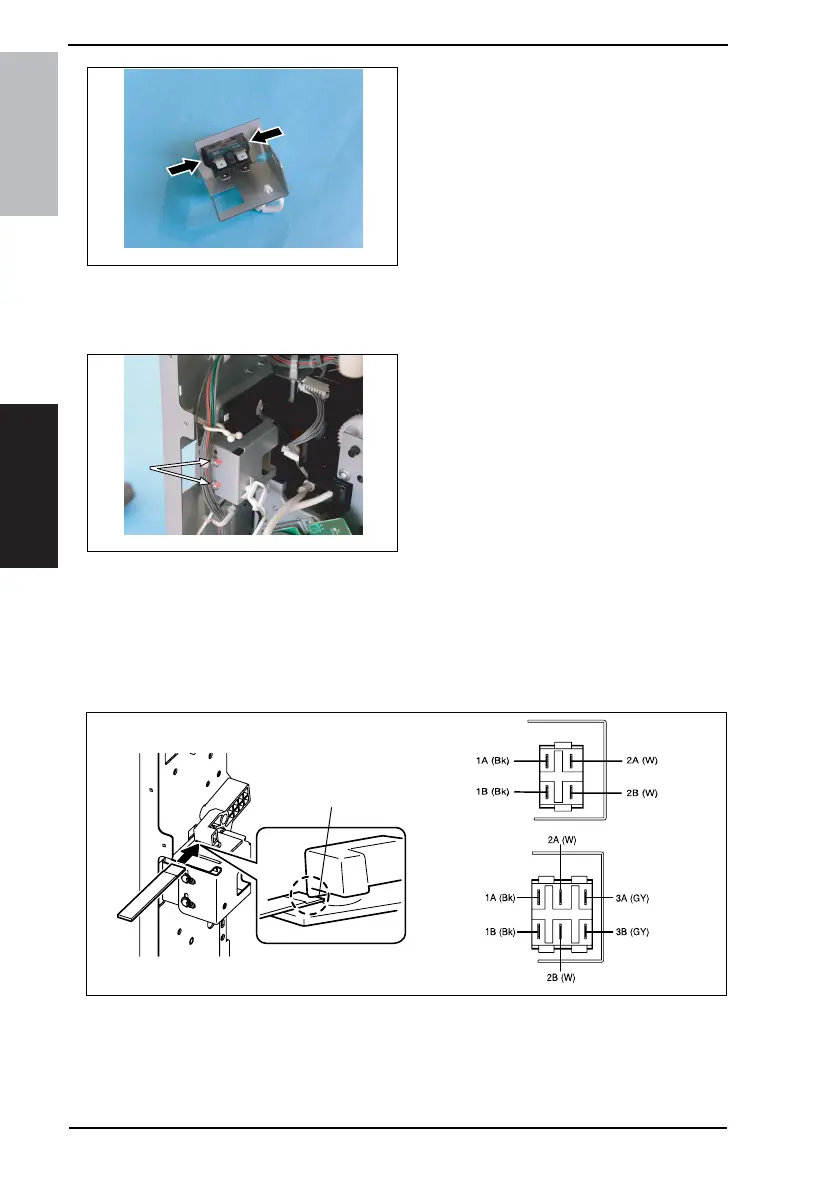
5. Unhook two tabs and remove the
Fusing Unit Interlock Switch.
<Fusing Unit Interlock Switch Reinstallation Procedure>
1. Fit the switch holder to the Fusing Unit Interlock Switch.
2. Connect the four connectors to the Fusing Unit Interlock Switch Assy.
3. Temporarily secure the Fusing Unit
Interlock Switch using two screws (to
which red paint has been applied).
4. With the right door closed, insert the gauge between the projection of lever and the top
surface of Fusing Unit Interlock Switch, and then secure the switch holder so that the
gap is 0.5 mm.
NOTE
• Use the 0.5 mm thick portion of gauge.
• Insert the gauge between the rear side (projection) of lever and the top surface of
Fusing Unit Interlock Switch.
for ineo 161
5. Close the right door, and then use a tester to make sure that the Fusing Unit Interlock
Switch is conducting between 2A and 2B.
6. Open the right door, and then use a tester to make sure that the Fusing Unit Interlock
Switch is not conducting between 2A and 2B.
4035D138AA
4035D131AA
Projection
4035D541AA
ineo 161
ineo 210
4035D540AA
4035D539AA