XBee‐PRO®900HP/XBee‐PRO®XSCRFModules
©2014DigiInternationalInc. 100
XBee‐PROXSCRFModuleOperation
Serial Communications
The XBee module interfaces to a host device through a CMOS-level asynchronous serial port. Through its
serial port, the module can communicate with any UART voltage compatible device or through a level
translator to any RS-232/485/422 device.
UART-Interfaced Data Flow
DevicesthathaveaUARTinterfacecanconnectdirectlythroughthepinsoftheXBeemoduleasshowninthe
figurebelow.
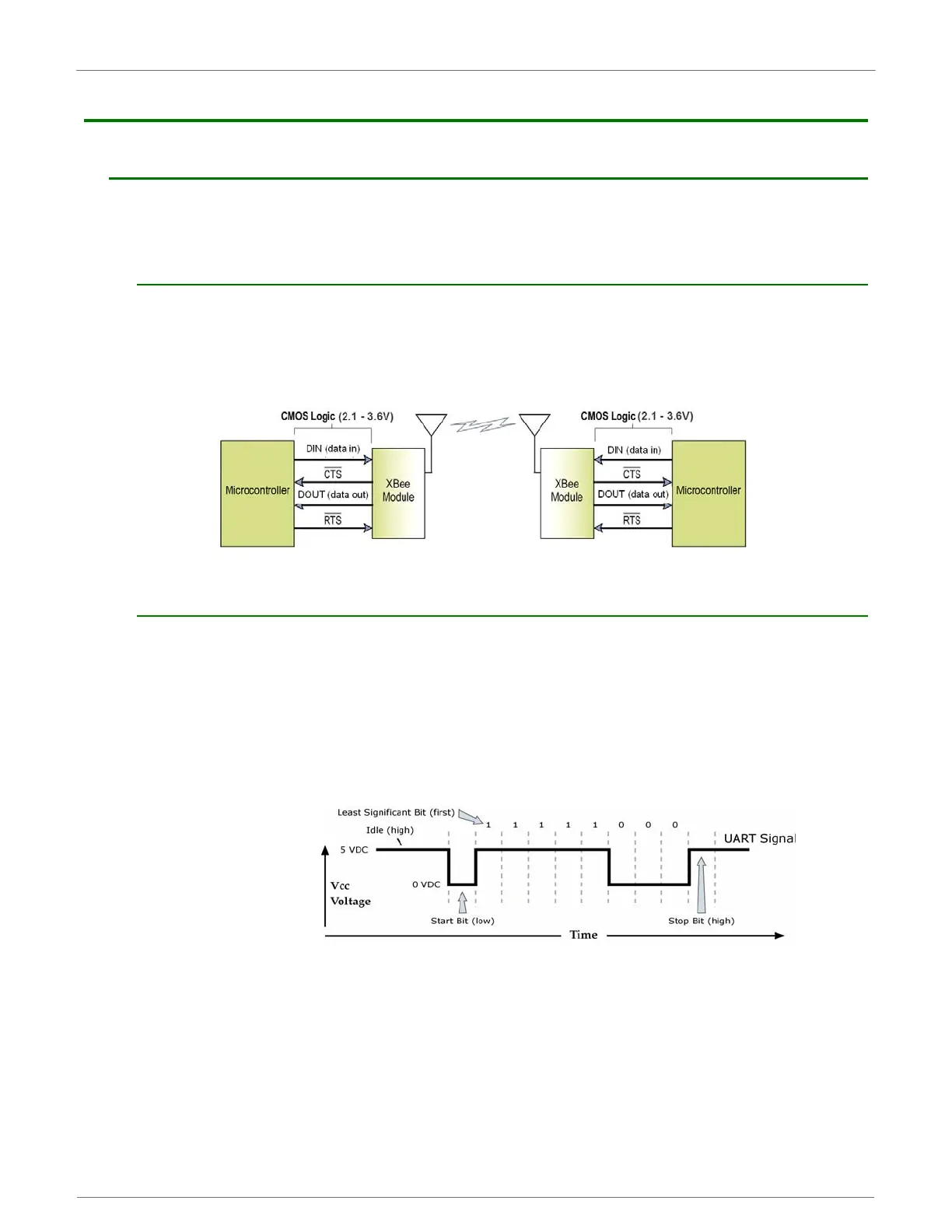
SystemDataFlowDiagraminaUART‐interfacedenvironment
(Low‐assertedsignalsdistinguishedwithhorizontallineoversignalname.)
Serial Data
Data enters the XBee module through the DI pin as an asynchronous serial signal. The signal should idle high
when no data is being transmitted.
The UART performs tasks, such as timing and parity checking, that are needed for data communications.
Serial communication consists of two UARTs, one being the XBee's and the other being the Microcontroller's,
configured with compatible parameters (baud rate, parity, start bits, stop bits, data bits) to have successful
communication. Each data packet consists of a start bit (low), 8 data bits (least significant bit first) and a stop
bit (high). The following figure illustrates the serial bit pattern of data passing through the module.
UARTdatapacket0x1F(decimalnumber“31”)astransmittedthroughtheXBeeModule
ExampleDataFormatis8‐N‐1(bits‐parity‐#ofstopbits)
 Loading...


