XBee‐PRO®900HP/XBee‐PRO®XSCRFModules
©2014DigiInternationalInc. 101
Flow Control
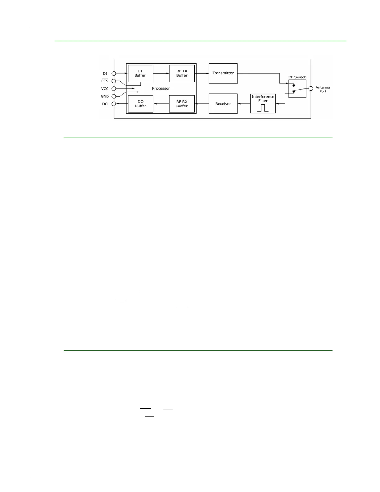
InternalDataFlowDiagram(Thefivemostcommonly‐usedpinsignalsshown.)
DI (Data In) Buffer and Flow Control
When serial data enters the XBee module through the DI Pin, then the data is stored in the DI Buffer until it
can be transmitted.
When the RO parameter threshold is satisfied (refer to Transmit Mode and Command Descriptions sections for
more information), the module attempts to initialize an RF connection. If the module is already receiving RF
data, the serial data is stored in the module's DI Buffer. If the DI buffer becomes full, hardware or software
flow control must be implemented in order to prevent overflow (loss of data between the host and XBee RF
Module).
How to eliminate the need for flow control:
• Send messages that are smaller than the DI buffer size, which is generally around 1,000
bytes.
• Interface at a lower baud rate (BD parameter) than the fixed RF data rate with the Retries
functionality (RR parameter) disabled.
Two cases in which the DI Buffer may become full and possibly overflow:
• If the serial interface data rate is set higher than the RF data rate of the module, the module
will receive data from the host faster than it can transmit the data over-the-air.
• If the module is receiving a continuous stream of data, monitoring data on a network, or
awaiting acknowledgments for Retries functionality, any serial data that arrives on the DI pin
is placed in the DI Buffer. The data in the DI buffer will be transmitted over-the-air when the
module no longer detects RF data in the network.
Hardware Flow Control (CTS
). When the DI buffer is 65 bytes away from being full; by default, the module
de-asserts (high) CTS
to signal to the host device to stop sending data [refer to FT (Flow Control Threshold)
and CS (DO2 Configuration) Commands]. CTS
is re-asserted after the DI Buffer has 34 bytes of memory
available.
Software Flow Control (XON). XON/XOFF software flow control can be enabled using the FL (Software Flow
Control) command.
DO (Data Out) Buffer and Flow Control
When RF data is received, the data enters the DO buffer and is then sent out the serial port to a host device.
Once the DO Buffer reaches capacity, any additional incoming RF data is lost.
Two cases in which the DO Buffer may become full and possibly overflow:
• If the RF data rate is higher than the set interface data rate of the module, the module will
receive data from the transmitting module faster than it can send the data to the host.
• If the host does not allow the RF module to send data out of the DO buffer because of hard-
ware or software flow control.
Hardware Flow Control (RTS
). If RTS is enabled for flow control (RT Parameter = 2), data will not be sent
out the DO Buffer as long as RTS
(pin 16) is de-asserted.
Software Flow Control (XOFF). XON/XOFF software flow control can be enabled using the FL (Software
Flow Control) Command. This option only works with ASCII data.
 Loading...


