XBee‐PRO®900HP/XBee‐PRO®XSCRFModules
©2014DigiInternationalInc. 31
When DigiMesh data is transmitted from one node to another, a network-level acknowledgement is
transmitted back across the established route to the source node. This acknowledgement packet indicates to
the source node that the data packet was received by the destination node. If a network acknowledgement is
not received, the source node will re-transmit the data.
See Data Transmission and Routing in chapter 4 for more information.
Receive Mode
If a valid RF packet is received, the data is transferred to the serial transmit buffer. This is the default mode
for the XBee radio.
Command Mode
To modify or read RF Module parameters, the module must first enter into Command Mode - a state in which
incoming serial characters are interpreted as commands. The API Mode section in Chapter 7 describes an
alternate means for configuring modules which is available with the SPI, as well as over the UART with code.
AT Command Mode
To Enter AT Command Mode:
Send the 3-character command sequence “+++” and observe guard times before and after the com-
mand characters. [Refer to the “Default AT Command Mode Sequence” below.]
Default AT Command Mode Sequence (for transition to Command Mode):
•No characters sent for one second [GT (Guard Times) parameter = 0x3E8]
•Input three plus characters (“+++”) within one second [CC (Command Sequence Character) parame-
ter = 0x2B.]
•No characters sent for one second [GT (Guard Times) parameter = 0x3E8]
Once the AT command mode sequence has been issued, the module sends an "OK\r" out the UART pin. The
"OK\r" characters can be delayed if the module has not finished transmitting received serial data.
When command mode has been entered, the command mode timer is started (CT command), and the
module is able to receive AT commands on the UART port.
All of the parameter values in the sequence can be modified to reflect user preferences.
NOTE: Failure to enter AT Command Mode is most commonly due to baud rate mismatch. By default,
the BD (Baud Rate) parameter = 3 (9600 bps).
To Send AT Commands:
Send AT commands and parameters using the syntax shown below.
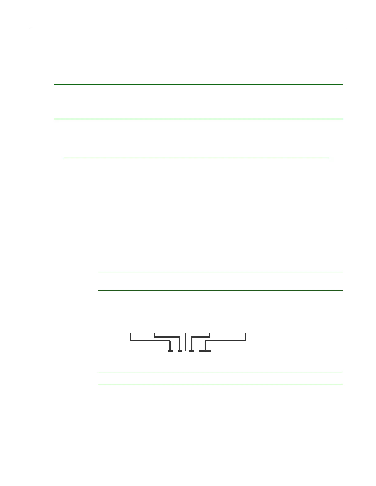
SyntaxforsendingATCommands
To read a parameter value stored in the RF module’s register, omit the parameter field.
The preceding example would change the RF module Destination Address (Low) to “0x1F”. To store the new
value to non-volatile (long term) memory, send the WR (Write) command. This allows modified parameter
values to persist in the module’s registry after a reset. Otherwise, parameters are restored to previously
saved values after the module is reset.
Example: ATDL 1F<CR>
“AT”
Prex
ASCII
Command
Space
(optional)
Parameter
(optional, HEX)
Carriage
Return
 Loading...


