XBee‐PRO®900HP/XBee‐PRO®XSCRFModules
©2014DigiInternationalInc. 22
2.XBee‐PRO900HPRFModuleOperation
XBee-PRO 900HP Basic Operational Design
The XBee-PRO
®
900HP RF Module uses a multi-layered firmware base to order the flow of data, dependent on the
hardware and software configuration chosen by the user. This configuration block diagram is shown below, with the
host serial interface as the physical starting point, and the antenna as the physical endpoint for the transferred data.
As long as a block is able to touch another block, the two interfaces can interact. For example, if the module is using
SPI mode, Transparent Mode is not available. See below:
The command handler is the code that processes commands from AT Command Mode or API Mode (see AT Com-
mands section). The command handler can also process commands from remote radios (see Remote AT Commands
section).
XBee-PRO 900HP Serial Communications
XBee RF Modules interface to a host device through a serial port. Through its serial port, the module can
communicate with any logic and voltage compatible UART, through a level translator to any serial device (for
example, through a RS-232 or USB interface board), or through a Serial Peripheral Interface (SPI), which is a
synchronous interface to be described later.
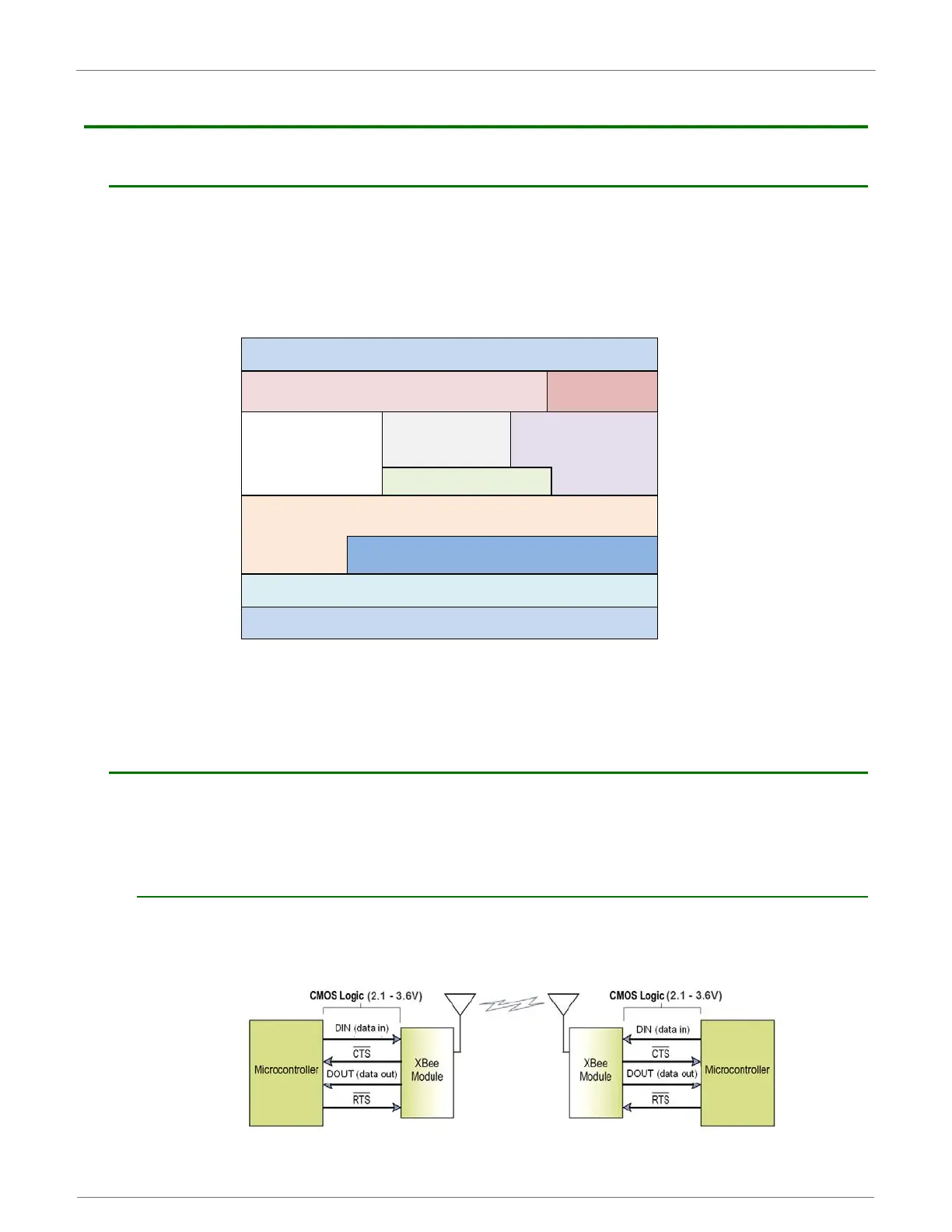
XBee-PRO 900HP UART Data Flow
Devices that have a UART interface can connect directly to the pins of the RF module as shown in the figure
below.
SystemDataFlowDiagraminaUART‐interfacedenvironment
(Low‐assertedsignalsdistinguishedwithhorizontallineoversignalname.)
Packet Handler
Transparent
Mode
Network Layer (DigiMesh/Repeater)
MAC/PHY Layer (Point-Multipoint)
UART SPI
Command Handler
Antenna
Host Serial Interface
 Loading...


