XBee‐PRO®900HP/XBee‐PRO®XSCRFModules
©2014DigiInternationalInc. 72
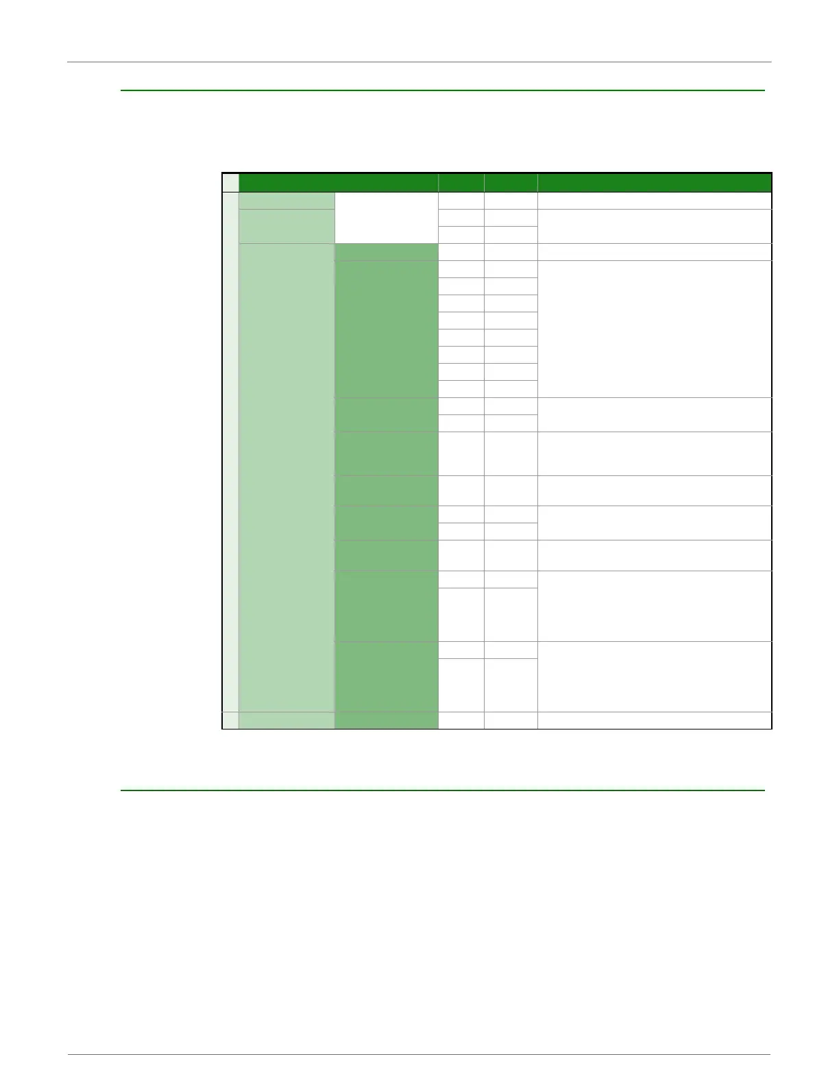
Data Sample RX Indicator
Frame Type: 0x92
When the modem receives an RF packet it is sent out the UART using this message type (when AO=1).
Node Identification Indicator
Frame Type:0x95
This frame is received when a module transmits a node identification message to identify itself (when AO=0).
The data portion of this frame is similar to a network discovery response frame (see ND command).
Frame Fields Offset Example Description
A
P
I
P
a
c
k
e
t
Start Delimiter 00x7E
Length
MSB 1 0x00
Number of bytes between the length and the checksum
LSB 2 0x14
Frame-specific Data
Frame Type 30x92
64-bit Source
(remote) Address
MSB 4 0x00
64-bit address to sender
50x13
60xA2
70x00
80x40
90x52
10 0x2B
LSB 11 0xAA
16-bit Source Network
Address
MSB 12 0x7D
16-bit address of sender
LSB 13 0x84
Receive Options 14 0x01
0x01 - Packet Acknowledged
0x02 - Packet was a broadcast packet
All other bits are reserved and should be ignored.
Number of Samples 15 0x01
Number of sample sets included in the payload.
(Always set to 1.)
Digital Channel Mask*
16 0x00
Bitmask field that indicates which digital IO lines on the
remote have sampling enabled (if any).
17 0x1C
Analog Channel
Mask***
18 0x02
Bitmask field that indicates which analog IO lines on the
remote have sampling enabled (if any).
Digital Samples (if
included)
19 0x00 If the sample set includes any digital IO lines (Digital
Channel Mask > 0), these two bytes contain samples for
all enabled digital IO lines. DIO lines that do not have
sampling enabled return 0. Bits in these 2 bytes map the
same as they do in the Digital Channels Mask field.
20 0x14
Analog Sample
21 0x02 If the sample set includes any analog input lines (Analog
Channel Mask > 0), each enabled analog input returns a
2-byte value indicating the A/D measurement of that
input. Analog samples are ordered sequentially from
AD0/DIO0 to AD3/DIO3, to the supply voltage.
22 0x25
Checksum 23 0xF5 0xFF - the 8 bit sum of bytes from offset 3 to this byte.
 Loading...


