XBee‐PRO®900HP/XBee‐PRO®XSCRFModules
©2014DigiInternationalInc. 73
Example: If the commissioning push button is pressed on a remote router device with 64-bit
address 0x0013a200407402ac and default NI string, the following node identification indicator
would be received: 0x7e 0025 9500 13a2 0040 7402 acff fec2 fffe 0013 a200 4074 02ac 2000 fffe
0101 c105 101e 000c 0000 2e33
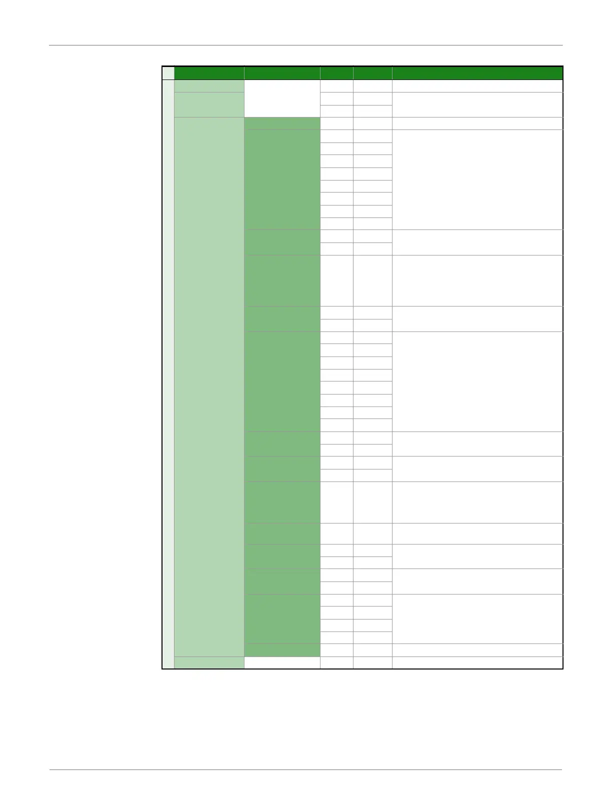
Frame Fields Offset Example Description
A
P
I
P
a
c
k
e
t
Start Delimiter 00x7E
Length
MSB 1 0x00
Number of bytes between the length and the checksum
LSB 2 0x25
Frame-specific Data
Frame Type 30x95
64-bit Source
Address
MSB 4 0x00
64-bit address of sender
50x13
60xA2
70x00
80x40
90x74
10 0x02
LSB 11 0xAC
Reserved
12 0xFF
Reserved.
13 0xFE
Receive Options 14 0xC2
0x01 - Packet Acknowledged
0x02 - Packet was a broadcast packet
0x40 - Point-multipoint packet
0x80 - Directed broadcast packet
0xC0 - DigiMesh packet
Reserved
15 0xFF
Reserved
16 0xFE
64-bit Address
MSB 17 0x00
Indicates the 64-bit address of the remote module that
transmitted the node identification frame.
18 0x13
19 0xA2
20 0x00
21 0x40
22 0x74
23 0x02
LSB 24 0xAC
NI String
25 0x20
Node identifier string on the remote device. The NI string
is terminated with a NULL byte (0x00).
26 0x00
Reserved
27 0xFF
Reserved
28 0xFE
Device Type 29 0x01
0=Coordinator
1=Normal Mode
2=End Device
(See the NO command description for more options)
Source Event 30 0x01
1=Frame sent by node identification pushbutton event
(See D0 command description)
Digi Profile ID
31 0xC1
Set to Digi’s application profile ID
32 0x05
Digi Manufacturer ID
33 0x10
Set to Digi’s Manufacturer ID
34 0x1E
Digi DD Value
(optional)
35 0x00
Reports the DD value of the responding module (this field
can be enabled with the NO command)
36 0x0C
37 0x00
38 0x00
RSSI (optional) 39 0x2E RSSI (this field can be enabled with the NO command)
Checksum 40 0x33 0xFF - the 8 bit sum of bytes from offset 3 to this byte.
 Loading...


