XBee‐PRO®900HP/XBee‐PRO®XSCRFModules
©2014DigiInternationalInc. 23
Serial Data
Data enters the module UART through the DIN (pin 3) as an asynchronous serial signal. The signal should
idle high when no data is being transmitted.
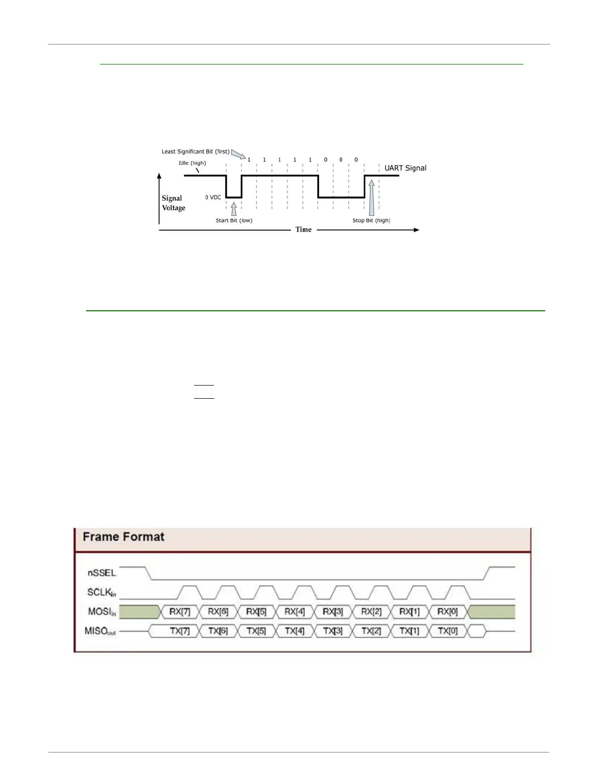
Each data byte consists of a start bit (low), 8 data bits (least significant bit first) and a stop bit (high). The
following figure illustrates the serial bit pattern of data passing through the module.
UARTdatapacket0x1F(decimalnumberʺ31ʺ)astransmittedthroughtheRFmodule
ExampleDataFormatis8‐N‐1(bits‐parity‐#ofstopbits)
Serial communications depend on the two UARTs (the microcontroller's and the RF module's) to be
configured with compatible settings (baud rate, parity, start bits, stop bits, data bits).
The UART baud rate, parity, and stop bits settings on the XBee module can be configured with the BD, NB,
and SB commands respectively. See the command table in chapter 10 for details.
XBee-PRO 900HP SPI Communications
The XBee modules support SPI communications in slave mode. Slave mode receives the clock signal and data
from the master and returns data to the master. The SPI port uses the following signals on the XBee:
• SPI_MOSI (Master Out, Slave In) - inputs serial data from the master
• SPI_MISO (Master In, Slave Out) - outputs serial data to the master
• SPI_SCLK (Serial Clock) - clocks data transfers on MOSI and MISO
•SPI_SSEL
(Slave Select) - enables serial communication with the slave
•SPI_ATTN
(Attention) - alerts the master that slave has data queued to send. The XBee mod-
ule will assert this pin as soon as data is available to send to the SPI master and it will remain
asserted until the SPI master has clocked out all available data.
In this mode, the following apply:
• SPI Clock rates up to 3.5 MHz are possible.
• Data is MSB first
• Frame Format mode 0 is used. This means CPOL=0 (idle clock is low) and CPHA=0 (data is
sampled on the clock’s leading edge). Mode 0 is diagramed below.
• SPI port is setup for API mode and is equivalent to AP=1.
FrameFormatforSPICommunications
 Loading...


