XBee‐PRO®900HP/XBee‐PRO®XSCRFModules
©2014DigiInternationalInc. 96
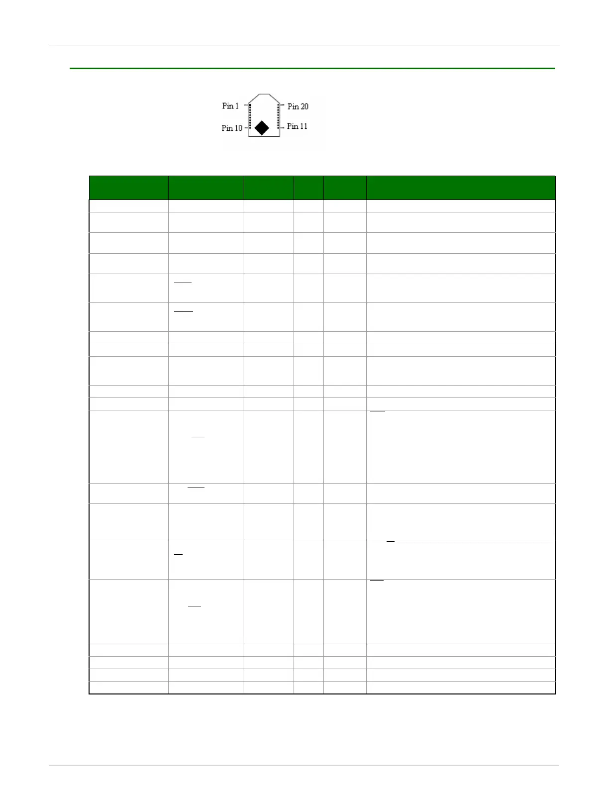
XBee-PRO XSC Pin Signals
XBee‐PROXSCRFModulePinNumbers(topview,shieldunderneath)
TableA‐02. J1PinSignalDescriptions
(Low‐assertedsignalsdistinguishedwithahorizontallineoversignalname.)
Note:*S3hasa100kpull‐up.S3Bhasinternalpull‐up.**S3has10kpull‐up.S3Bhasinternalpull‐up.
Module Pin Public Signal Notes I/O
When
Active
Function
1 VCC I Supply Voltage
2 DO (Data Out) O n/a
Serial data exiting the module (to the UART host). Refer to the
Serial Communications section for more information
3 DI (Data In I n/a
Serial data entering the module (from UART host). Refer to the
Serial Communications section for more information.
4 DO3 / RX LED O high
Pin is driven high during RF data reception; otherwise, the pin is
driven low. Refer to the CD Command section to enable.
5 Reset
**Has a pull up
resistor
I/O low
Re-boot module.(minimum pulse is 90us) Open Drain
configuration. Module will drive reset line low momentarily on
reboot and power up.
6 Config
*Has a pull up
resistor
I low / high
Pin can be used as a backup method for entering Command
Mode during power-up. Primary method is with “+++”. Refer to
the AT Commands section for more information.
7 O Driven high Do not Connect
8 NC Do not Connect
9 DI3 / SLEEP
*Has a pull up
resistor
Ihigh
By default, DI3 pin is not used. To configure this pin to support
Sleep Modes, refer to the Sleep Mode, SM Command and PW
Command sections.
10 GND Ground
11 O Driven high Do not Connect
12
DO2 / CTS
/ RS-485
Enable
Olow
CTS
(clear-to-send) flow control - When pin is driven low, UART
host is permitted to send serial data to the module. Refer to the
Serial Communications and CS Command sections for more
information.
----------------------------------------------------------------
RS-485 Enable - To configure this pin to enable RS-485 (2-wire
or 4-wire) communications, refer to the Serial Communications
and CS Command sections.
13 ON / Sleep
Ohigh
high = Indicates power is on and module is not in Sleep Mode.
Low = Sleep mode or module is unpowered
14 VREF I n/a
Not used on this module. For compatibility with other XBee
modules, we recommend connecting this pin to a voltage
reference if Analog sampling is desired. Otherwise, connect to
GND.
15 TX
/ PWR O n/a
low = TX
- Pin pulses low during transmission
--------------------------------------------------------------
high = PWR - Indicates power is on and module is not in Sleep
Mode
16 DI2 / RTS
/ CMD
*Has a pull
down resistor
Ilow
RTS
(request-to-send) flow control - By default, this pin is not
used. To configure this pin to regulate the flow of serial data
exiting the module, refer to the Serial Communications and RT
Command sections.
---------------------------------------------------------------
CMD -Refer to Binary Commands and RT Command sections
to enable binary command programming.
17 O Driven low Do not Connect
18 O Driven low Do not Connect
19 O Driven low Do not Connect
20 O Driven low Do not Connect
 Loading...


