XBee‐PRO®900HP/XBee‐PRO®XSCRFModules
©2014DigiInternationalInc. 97
Xbee-PRO XSC Electrical Characteristics
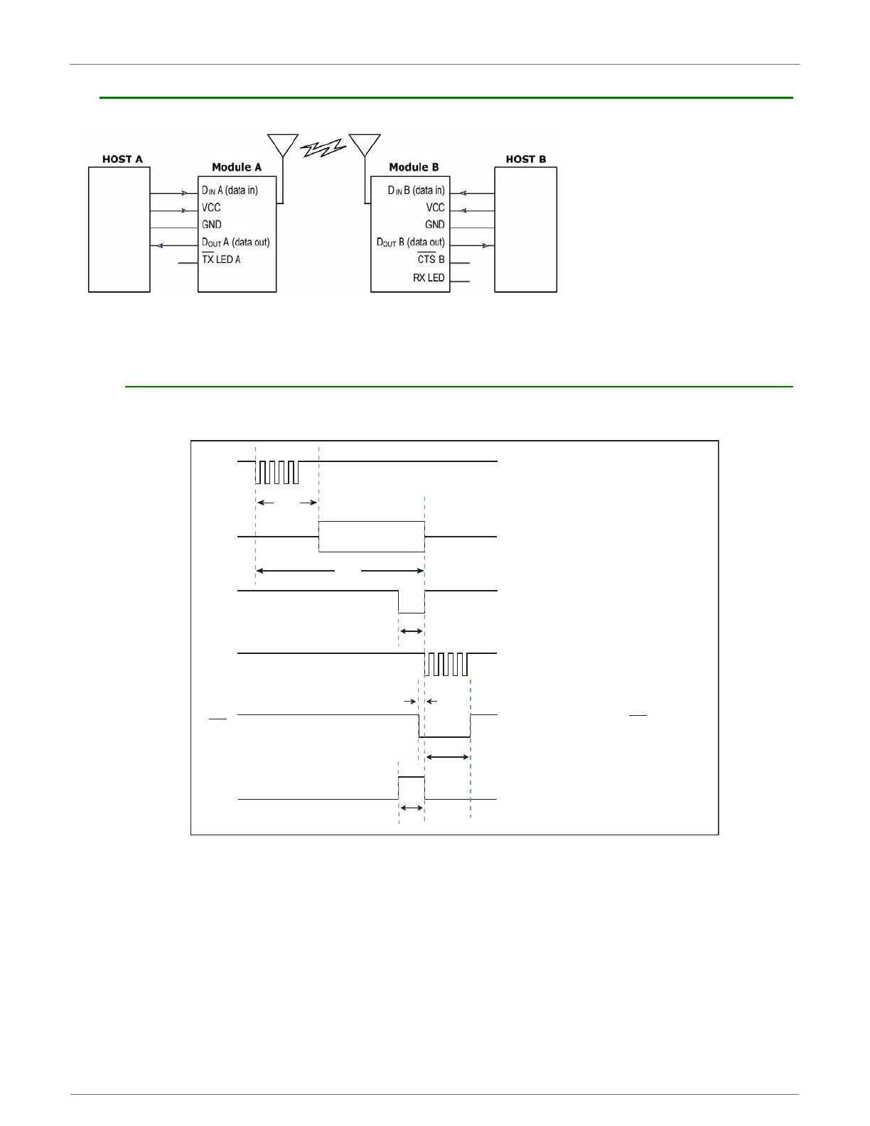
SystemBlockDiagramBasicwirelesslinkbetweenhosts
The data flow sequence is initiated when the first byte of data is received in the DI Buffer of the transmitting
module (XBee Module A). As long as XBee Module A is not already receiving RF data, data in the DI Buffer is
packetized, then transmitted over-the-air to XBee Module B.
XBee-PRO XSC Timing Specifications
TimingSpecifications(“A”and“B”refertoFigure.)
A Transmits over air
B Receives
T
ST
T
TX
T
TL
T
RL
Host A sends serial data to XBee Module A
After T , contents of D Buffer
are assembled into packet and transmitted
IN
TX/PWR LED on XBee Module A pulses off
briefly to indicate RF transmission
If 16-bit CRC checks out, data is shifted out
serial port to Host B
(Optional) Set ATCS = 1 to use CTS as RS-485
TX enable low-asserted signal
RX LED pulses on briefly to indicate RF reception
DA
IN
RF A
OUT
TX LED A
D B
OUT
RX LED B
CTS B
ST
T
CLDL
T
CHDH
 Loading...


