XBee‐PRO®900HP/XBee‐PRO®XSCRFModules
©2014DigiInternationalInc. 84
If the IS command is issued from AT command mode then a carriage return delimited list will be returned
containing the above-listed fields. If the command is issued via an API frame then the module will return an
AT command response API frame with the IO data included in the command data portion of the packet.
Periodic I/O Sampling
Periodic sampling allows an XBee-PRO module to take an I/O sample and transmit it to a remote device at a
periodic rate. The periodic sample rate is set by the IR command. If IR is set to 0, periodic sampling is
disabled. For all other values of IR, data will be sampled after IR milliseconds have elapsed and transmitted to
a remote device. The DH and DL commands determine the destination address of the IO samples. Only
devices with API mode enabled will send IO data samples out their serial interface. Devices not in API mode
will discard received IO data samples.
2 Digital Channel Mask
Indicates which digital IO lines have sampling enabled. Each bit corresponds to one
digital IO line on the module.
• bit 0 = AD0/DIO0
• bit 1 = AD1/DIO1
• bit 2 = AD2/DIO2
• bit 3 = AD3/DIO3
• bit 4 = DIO4
• bit 5 = ASSOC/DIO5
•bit 6 = RTS/DIO6
•bit 7 = CTS/GPIO7
• bit 8 = DTR / SLEEP_RQ / DIO8
• bit 9 = ON_SLEEP / DIO9
• bit 10 = RSSI/DIO10
• bit 11 = PWM/DIO11
• bit 12 = CD/DIO12
For example, a digital channel mask of 0x002F means DIO0,1,2,3, and 5 are enabled
as digital IO.
1 Analog Channel Mask
Indicates which lines have analog inputs enabled for sampling. Each bit in the analog
channel mask corresponds to one analog input channel.
•bit 0 = AD0/DIO0
•bit 1 = AD1/DIO1
•bit 2 = AD2/DIO2
•bit 3 = AD3/DIO3
Variable Sampled Data Set
If any digital IO lines are enabled, the first two bytes of the data set indicate the state
of all enabled digital IO. Only digital channels that are enabled in the Digital Channel
Mask bytes have any meaning in the sample set. If no digital IO are enabled on the
device, these 2 bytes will be omitted.
Following the digital IO data (if any), each enabled analog channel will return 2 bytes.
The data starts with AIN0 and continues sequentially for each enabled analog input
channel up to AIN5.
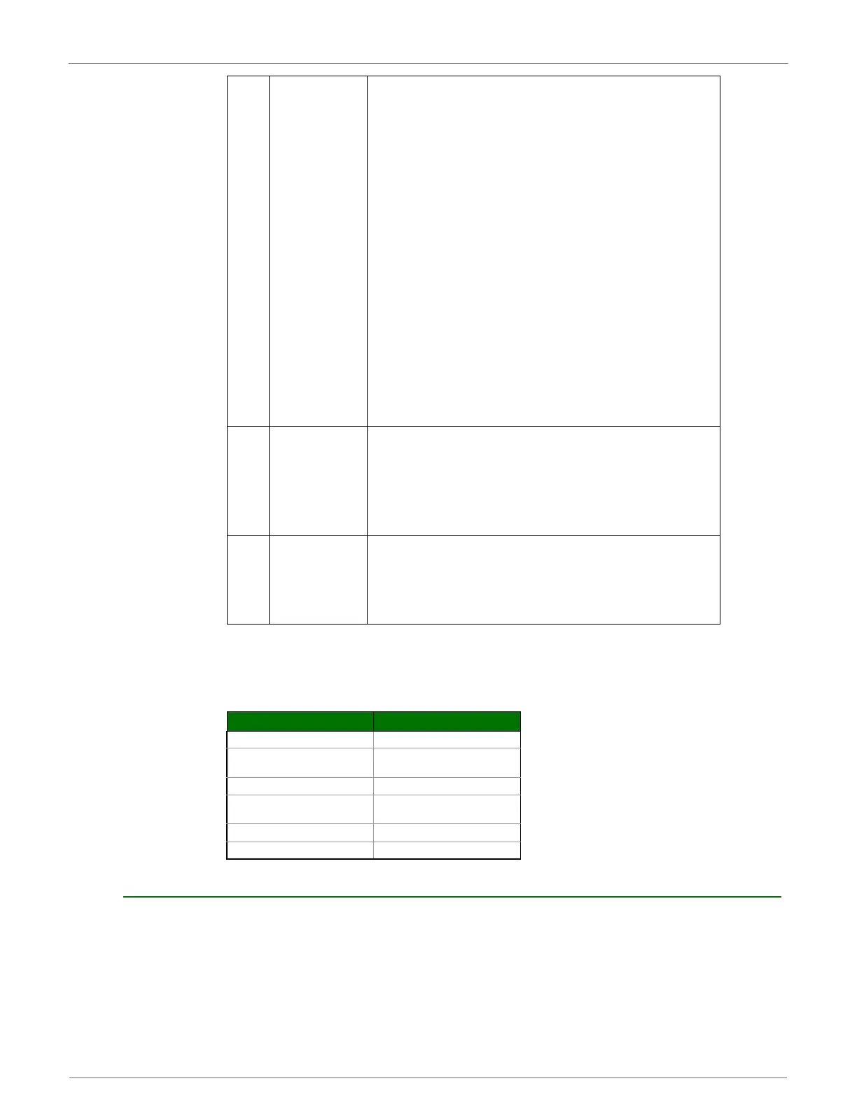
Example Sample AT Response
0x01\r [1 sample set]
0x0C0C\r
[Digital Inputs: DIO 2, 3, 10, 11
enabled]
0x03\r [Analog Inputs: A/D 0, 1 enabled]
0x0408\r
[Digital input states: DIO 3, 10
high, DIO 2, 11 low]
0x03D0\r [Analog input ADIO 0= 0x3D0]
0x0124\r [Analog input ADIO 1=0x120]
 Loading...


