XBee‐PRO®900HP/XBee‐PRO®XSCRFModules
©2014DigiInternationalInc. 98
TypicalACCharacteristics(SYparameter=0,symbolscorrespondtoFigureandFigure.)
DCCharacteristics(Vcc=3.0‐3.6VDC)
Note:*MinVoltageforS3Bis2.1v,howeverMaxPowerwillbereducedandSensitivitymaydegrade.
**S3istolerantupto5.5voninputpins.
***S3Bcanhavepull‐
upsenabledandstillmaintainlowleakagecurrent.
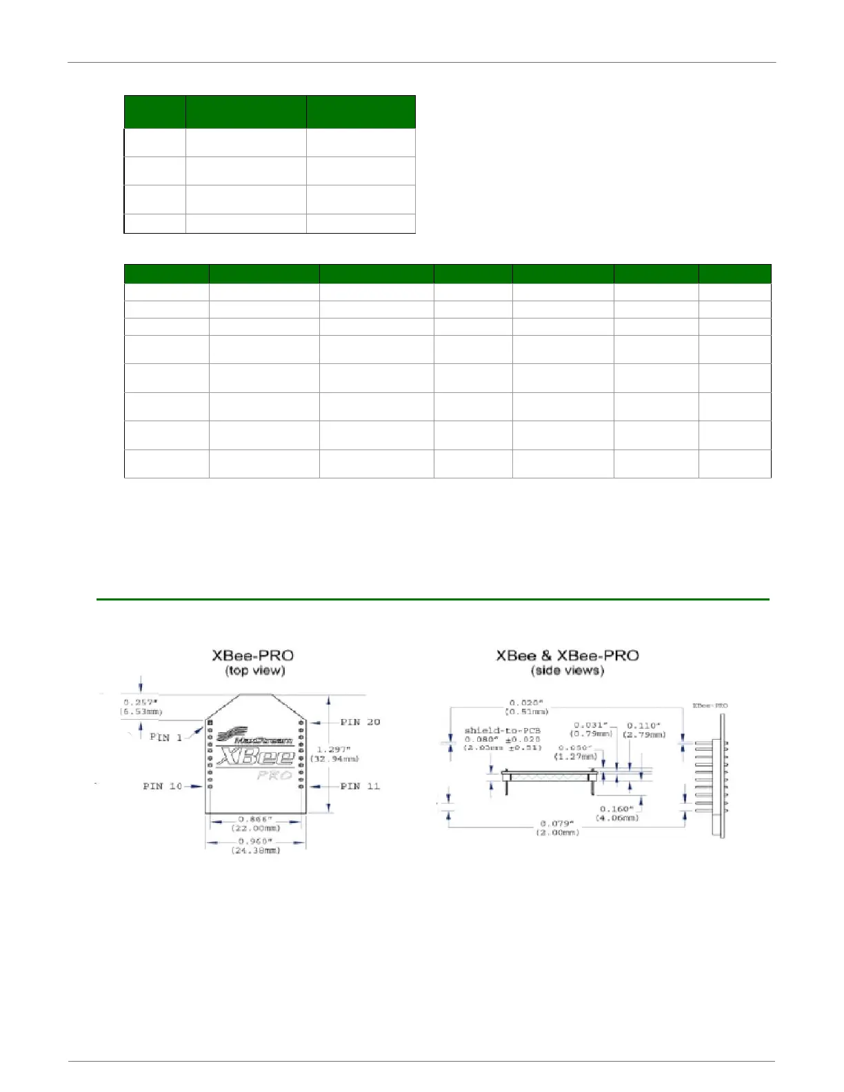
XBee-PRO XSC Mechanical Drawings
MechanicalDrawings
Symbol Description
9600 baud rate
(32 byte packet)
T
TX
Latency from the time data
is transmitted until received
72.0 ms
T
TL
Time that TX/PWR pin is
driven low
16.8 ms
T
RL
Time that RX LED pin is
driven high
25.6 ms
T
ST
Channel Initialization Time 35.0 ms
Symbol Parameter Condition Min Typical Max Units
Vcc
Module Supply Voltage *3.0 3.6 V
VIL
Input Low Voltage All input signals -0.3 0.3Vcc V
VIH
Input High voltage All input signals 0.7Vcc Vcc + 0.3 ** V
VOL
Output Low-Level
Voltage
Iout = Iout_Max 0.4 V
VOH
Output High-Level
Voltage
Iout = Iout_Max Vcc-0.4 V
IL
Input Leakage Current
***With Pull-up resistors
disabled
40 400 nA
IO1
Output Current
pins 2, 15 (Dout, ~TX/
Pwr)
2mA
IO2
Output Current
pins 4, 12, 13
(DCD,~CTS,ON/~Sleep)
8mA
 Loading...


