XBee‐PRO®900HP/XBee‐PRO®XSCRFModules
©2014DigiInternationalInc. 107
nal’ tab (or other serial communications software) of the X-CTU Software can be used to enter
the sequence.
[OR]
• Assert (low) the CONFIG
pin and either turn the power going to the module off and back on.
(If using a Digi XBIB-R Interface Board, the same result can be achieved by holding the Data-
In line low (also known as a break) while rebooting the module by pressing the reset button
on the module assembly [module assembly = module mounted to an interface board]).
Default AT Command Mode Sequence (for transition to Command Mode):
• No characters sent for one second [refer to the BT (Guard Time Before) Command]
• Input three plus characters (“+++”) within one second
[refer to the CC (Command Sequence Character) Command.]
• No characters sent for one second [refer to the AT (Guard Time After) Command.]
To Send AT Commands:
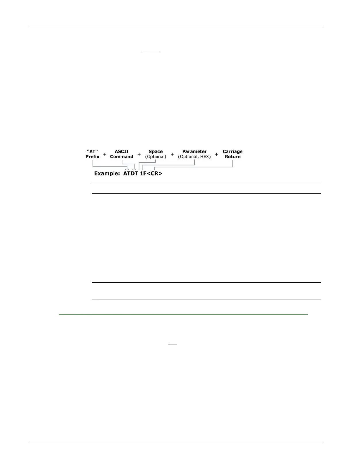
Send AT commands and parameters using the syntax shown below.
FigureA‐1.SyntaxforsendingATCommands
To read a parameter value stored in the module register, leave the parameter field blank.
The preceding example would change the module’s Destination Address to “0x1F”. To store the new value to
non-volatile (long term) memory, the Write (ATWR) command must subsequently be sent before powering off
the module.
System Response. When a command is sent to the module, the module will parse and execute the
command. Upon successful execution of a command, the module returns an “OK” message. If execution of a
command results in an error, the module returns an “ERROR” message.
To Exit AT Command Mode:
• If no valid AT Commands are received within the time specified by CT (Command Mode Time-
out) Command, the module automatically returns to Idle Mode.
[OR]
• Send ATCN (Exit Command Mode) Command.
For an example of programming the RF module using AT Commands and descriptions of each config-
urable parameter, refer to the “RF Module Configuration” chapter.
Binary Commands
Sending and receiving parameter values using binary commands is the fastest way to change operating
parameters of the module. Binary commands are used most often to sample signal strength (RS parameter)
and/or error counts; or to change module addresses and channels for polling systems when a quick response
is necessary. Since the sending and receiving of parameter values takes place through the same data path as
'live' data (received RF payload), follow the CTS
pin as outlined in Figure 2-012 to distinguish between the
two types of data (commands vs 'live' data).
Common questions regarding the use of binary commands:
• What are the implications of asserting CMD while live data is being sent or received?
• After sending serial data, is there a minimum time delay before CMD can be asserted?
• Is a time delay required after CMD is de-asserted before payload data can be sent?
• How to discern between live data and data received in response to a command?
CMD (pin 16) must be asserted in order to send binary commands to the module. The CMD pin can be
asserted to recognize binary commands anytime during the transmission or reception of data. The status of
the CMD signal is only checked at the end of the stop bit as the byte is shifted into the serial port. The
 Loading...


