CT100 inverter Detailed instructions of function parameters
99
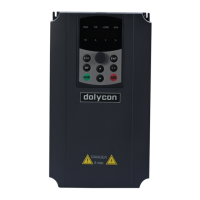
Figure 6-3 V/F curve
Setting range: 0.0 % (automatic)
0.1%~10.0% (manual)
Torque
compensation
cut-off
Setting range: 0.0%~50.0%
F03.01 Torque compensation
Refer to the motor rated voltage (F01.05) to set the voltage compensation at zero
frequency.
F03.02 Torque compensation cut-off
Refer to the motor rated frequency (F01.03) to set the torque compensation
cut-off frequency.
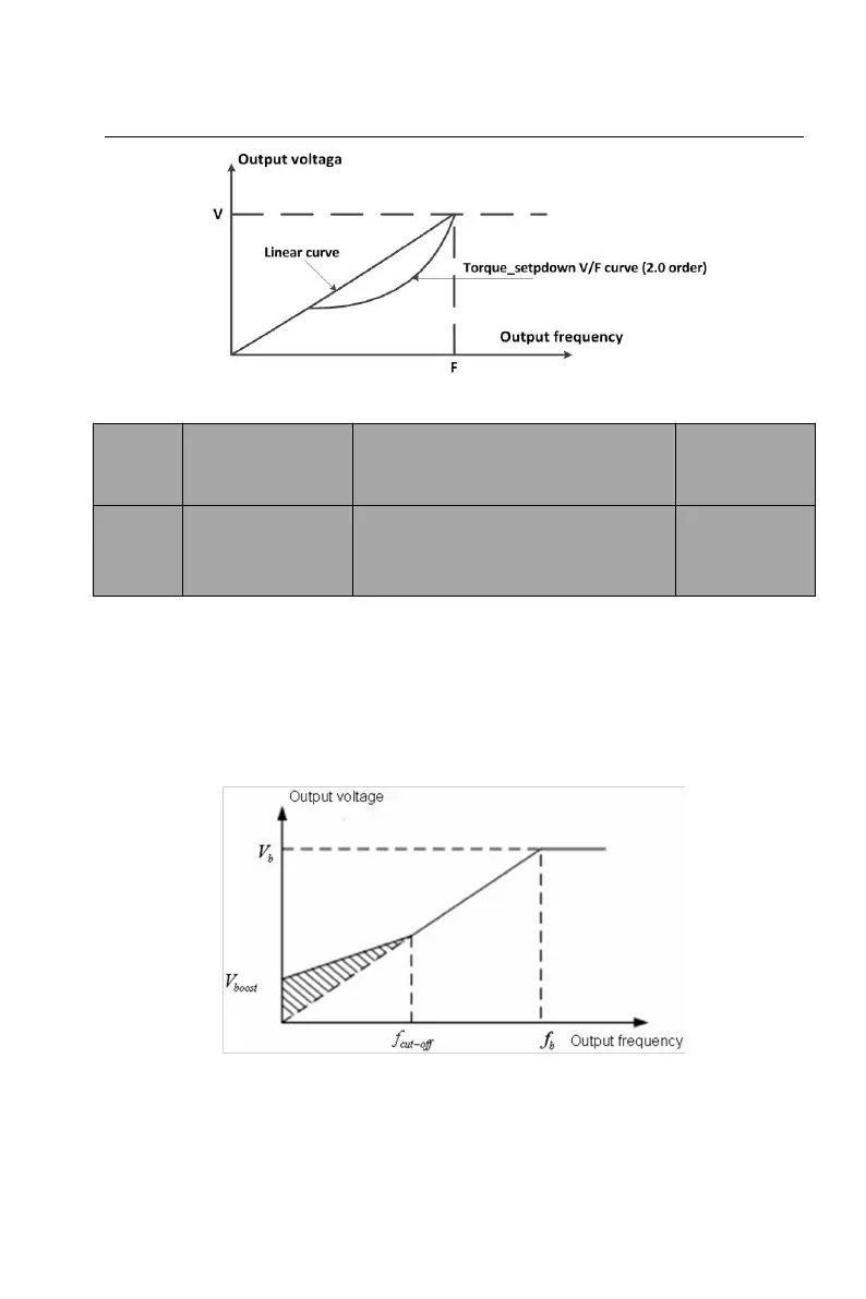
Figure 6-4 Torque compensation plot
Torque compensation can improve the V/F low-frequency torque characteristic.
When the inverter is running below the torque compensation cut-off
(F03.02*motor rated frequency), by increasing the output voltage, offsetting the
 Loading...