CT100 inverter Detailed instructions of function parameters
100
stator voltage drop and generate enough torque, ensure the motor runs normally.
The torque compensation amplitude should be set appropriately according to the
load conditions, excessive compensation in startup will cause a great current
impact.
Setting range: 0.00~F03.05
Setting range: 0.0% ~
100.0%
Setting range: F03.03 ~
F03.07
Setting range: 0.0% ~
100.0%
Setting range: F03.05 ~
F01.03
Setting range: 0.0% ~
100.0%
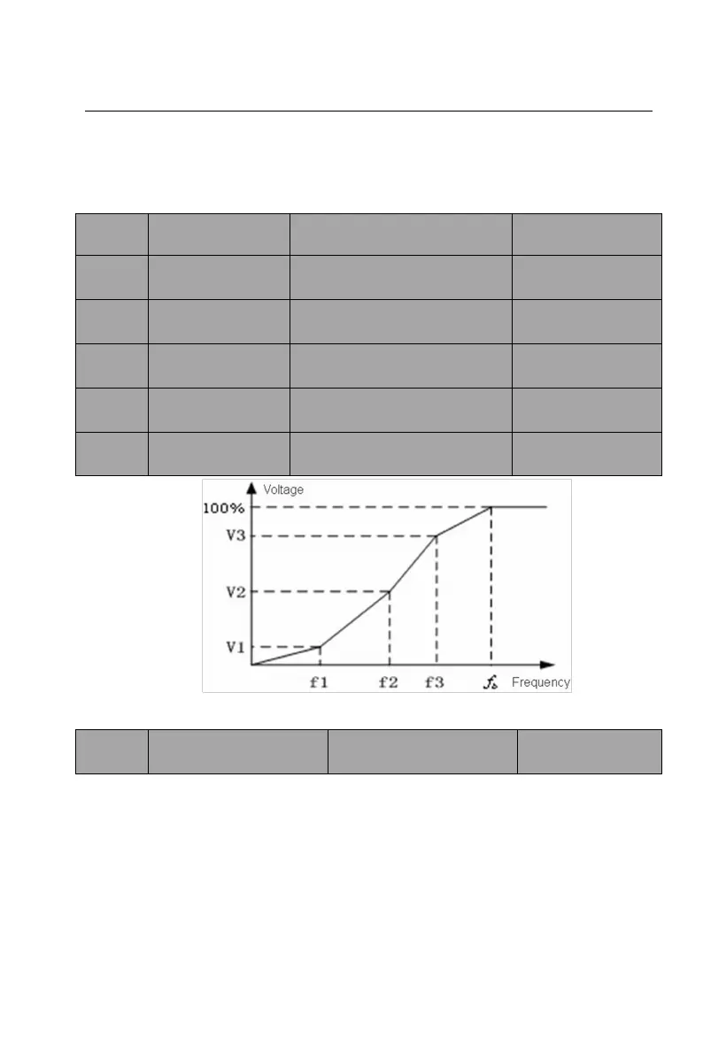
Figure 6-5 Multi-dots V/F curve
Setting range: 0.0 ~
200.0%
The motor’s running torque changes with the load torque, which results in the
variance of motor speed. The inverter’s output frequency can be adjusted
automatically through slip compensation according to the load torque. Therefore
the change of speed due to the load change can be reduced.
Slip compensation frequency = sign * F03.09 * slip frequency * torque
current/motor rated current, electric state symbol is +, power generation status
symbol is -.
 Loading...