CT100 inverter Detailed instructions of function parameters
115
Setting range: -10.00 ~
10.00V
Corresponding setting
of AI2 upper limit
Setting range: -100.0 ~
100.0%
Setting range: 0.00 ~
10.00s
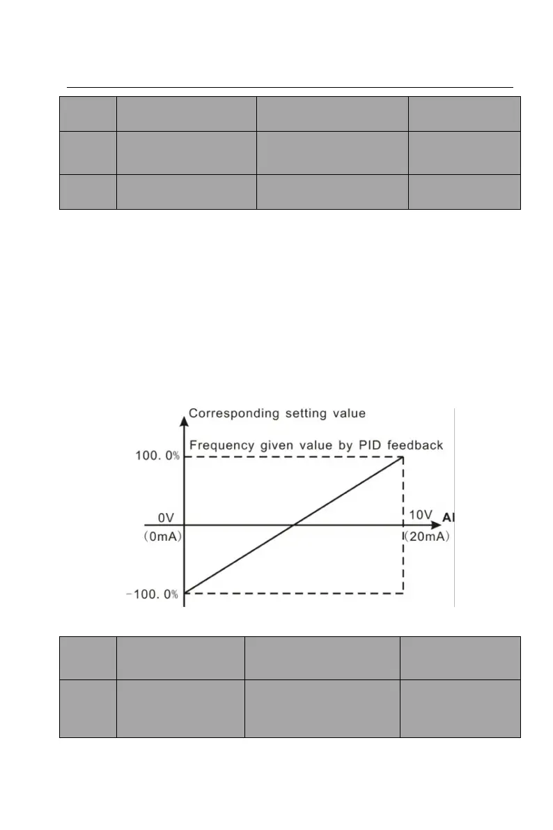
The parameters determine the relationship between input voltage and the
corresponding setting value. When the analog input voltage exceeds the range
between lower limit and upper limit, it will be regarded as the upper limit or lower
limit.
Input filter time: the larger the value, the stronger the anti-interference capability
and the lower the sensitivity; the smaller the value, the higher the analog input
sensitivity and the weaker the anti-interference capability.
Analog AI1~AI2 can support 0~10V/0~20mA input through the external DIP
switch selection, for 0~20mA input, 20mA corresponds to 5V.
The following figure is about the relationship between analog input and
corresponding setting.
F
igure 6-11 Relationship between analog input and corresponding setting
Setting range: 0.00 ~
50.00kHz
Corresponding
setting of HDI lower
limit frequency
Setting range: -100.0 ~
100.0%