The DRAGFLOW EL7.5 - EL12.5 (S - SS) is an electric motor-driven pump designed for dredging operations, specifically for pumping underwater mixtures of water and solid materials such as sand, mud, and rocks of suitable dimensions. Its primary function is to move these solids efficiently, even in aggressive environments.
Function Description
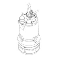
The pump consists of a cylindrical motor housing [3] that encloses an electrical motor [B]. The upper support [40] is watertight and contains the terminal box for electrical connections, with waterproofing ensured by a cover and a series of seals [D]. An oil chamber/casing [4] houses a group of mechanical seals [F] that prevent water from entering the motor.
A keyed impeller [1], made from high-chrome anti-wear materials, is located on the main shaft [2] within the oil chamber/casing [4]. A lower wear plate [7], also made from the same material, partially covers the impeller inlet. Inside the strainer protection [50], an agitator [10] rotates to stir the mixture of solids in the water, facilitating pumping.
The pump requires connection to a power source (such as a power generator) and a control panel to operate. It is crucial that these electrical devices are suitable for the pump's electrical specifications (voltage, power, absorption, frequency) and comply with international safety standards. The pump itself does not have an Emergency Stop button; any electrical system used for power supply must include one that instantly disconnects power and keeps the pump disconnected without resetting.
Important Technical Specifications
- Electrical Data: The pump's identification plate (Fig. 2) specifies maximum values for AMP (current absorption) and HP/KW (power), which should not be exceeded during continuous operation. The VOLT (voltage) value is nominal, and variations exceeding 10% during continuous operation should be avoided.
- Dimensions and Weight: Refer to the data-sheet in the Attachments chapter for specific dimensions and weight.
- Materials: Key components like the impeller [1] and lower wear plate [7] are made from high-chrome anti-wear materials, suitable for abrasive dredging conditions.
- Lubricating Oil: The recommended lubricating oil is PETRONAS HYDROBAK 32, an ISO VG 32 oil with a density of 0.865-0.885 g/cm³ at 15°C, viscosity of 28.8-35.2 cSt at 40°C, and a flash point ≥200°C (Tab. 3).
- Lubricating Grease: The recommended lubricating grease is TECNOLUBE POLYMER 400/2, a mineral-based grease with PTFE, lithium complex thickener, operating temperature range of -20/+125°C, washout resistance of 2.8% (1hr - 38°C), dropping point >267°C, flash point 277°C, density of 0.899 g/cm³ at 25°C, and viscosity of 142 cSt at 40°C (Tab. 4).
- Bolts Tightening Torque: A table (Tab. 2) provides suggested tightening torques (Ts in N·m) for common bolt sizes (d in mm), ranging from 39 N·m for M12 (4.6 grade) to 1885 N·m for M30 (10.9 grade).
Usage Features
- Installation: Installation requires skilled operators for suspended loads handling, mechanical assembly, and electrical wiring. Operations may involve deep water, wet surfaces, and suspended loads risks, necessitating appropriate personal protective equipment. Delivery pipes must be connected to the pump's exit flange, avoiding siphons (Fig. 4) to prevent air pockets or solid material deposits.
- Electrical Connection: Before connecting to the electrical source, ensure it is shut down and de-energized. The ground wire (yellow/green) must always be connected to the plant's general grounding system, ensuring electrical conductivity between the pump and the main grounding system. The correct rotation of the pump depends on the three-phase connection order; if incorrect, two phases on the control panel terminal board should be switched.
- First Start-up: Before the first start, check the lubricating oil level by slightly unscrewing the "OIL" plug [A] (Fig. 5). If no oil drips out, refill the oil chamber. Also, check the tightness of the agitator [10] and its threaded components (connector [11], nut [12], spacer [13], impeller [1]) (Fig. 6).
- Rotation Check: For a short period (max 10 seconds), start the pump out of water in a stable position to check its rotation against the red arrow on the plate (Fig. 7). If incorrect, switch two phases on the control panel terminal board.
- Working Operations: The pump should be completely submerged in clean water before starting. Once a full flow of clean water exits the discharge line, slowly lower the pump into contact with the material. During operation, maintain contact with the material, avoid pushing the pump too hard, and do not dredge in the same spot for extended periods to prevent getting stuck. Monitor the percentage of solids and current absorption to stay within limits.
- Stopping: Before stopping, lift the pump from the material and pump clean water to flush the pipes and prevent clogging.
- Emergency: In case of danger, press the Emergency Stop button, identify and resolve the fault, and only reset the button after the area is clear.
Maintenance Features
- General Safety: All maintenance operations must be performed with the power supply shut off and movable devices stopped. The pump should be clean, stable, and in a suitable area. Qualified operators must perform maintenance, wearing appropriate personal protective equipment.
- Tools: Ordinary maintenance requires a set of dynamometric wrenches (up to 1000 Nm), Allen keys (1.5 to 10), a steel hammer, a rubber hammer, a wood piece, Seeger pliers, parrot pliers, screwdrivers (flat and cross head), a multimeter, and an RPM counter (Fig. 8-15).
- Maintenance Schedule:
- Before every shift: Check power cable and waterproofing, listen for anomalous noise/vibration (briefly starting out of water), check Emergency Stop functionality, and inspect lifting points/equipment (Tab. 5).
- After every shift: Clean the pump's inlet zone, remove clogging, and wash external surfaces with clean water (Tab. 6).
- During every shift: Monitor pump performance (amperage, slurry production) and keep the control panel and working area clean and dry (Tab. 7).
- Every 8 operating hours: Check lubricating oil quantity and condition (Fig. 19). If oil is deteriorated or contains impurities/water, replace it and consider replacing seals.
- Every 50 operating hours: Check tightness of bolts and other threaded components, and inspect the agitator kit (Tab. 9).
- Every 150 operating hours: Check impeller clearance between the lower wear plate [7] and the impeller [1] using a feeler gauge; it should not exceed 1 mm (Fig. 21). If it does, adjust the clearance.
- Lubricating Oil Changing/Refilling: Place the pump horizontally with the "OIL" plug [A] pointing down. Remove the plug and copper washer to drain old oil (Fig. 20). Refill the oil chamber with approximately 5 kg of new oil, then reassemble and tighten the plug, checking the copper washer. Dispose of old oil responsibly.
- Impeller Clearance Adjusting: Place the pump vertically and overturned, remove the strainer. Loosen the three adjusting bolts [206] to allow the wear plate to contact the impeller (Fig. 23a). Screw the adjusting bolts until a 1 mm clearance is achieved (using three feelers at 120° on the inlet hole diameter) (Fig. 23b). Fix the wear plate by tightening the three nuts [401] while blocking the adjusting bolts [206], then remove the feelers (Fig. 24a). Finally, block the wear plate by tightening the three bolts [205] (Fig. 24a).
- Component Replacement: A table (page 44) outlines the disassembling sequence for replacing components like the power cable, strainer, lower wear plate, agitator kit, impeller, motor bearing, lower seals, mechanical seals, and upper bearings. Operations marked with an asterisk (*) require the manufacturer's Service Department or a skilled mechanical operator. Before any replacement involving the oil chamber, completely empty the pump of oil.
- O-ring Replacement: It is good practice to replace any O-ring disassembled during maintenance, even if it appears in good condition. Lubricate new O-rings and clean their seats before positioning.
Optional Devices
- Jet-ring system: Helps move solids underwater by creating a well-oriented jet of clean water, improving dredging efficiency. Requires a water pressure supply (8 bar, 20 mc/h flow rate).
- Compensation system: Required for depths greater than 25 meters. Consists of a protected rubber bag filled with oil to balance inner and outer hydrostatic pressure, protecting the pump's sealing system.
- Temperature sensor: Monitors working temperature and can stop the pump if a set-point value (default 150°C) is exceeded.
- Cutter knife: An optional device installed on the main shaft, replacing the connector, designed to cut and minimize soft/fibrous solids like wood pieces or seaweed.
- Water sensor, Cooling jacket, Waterflush kit, Remote greasing kit: Not available for this specific pump model.