DRAGFLOW S.r.l. - Sede legale: Via Satiro, 11 – 37121 VERONA Italy
Sede amm.: Via Paesa – 46048 ROVERBELLA (MN) Italy ● Tel. +39 0376 1685400
Fax +39 0376 1685499 - Cod. Fisc e P. IVA : IT 02757460239 – R.E.A. Verona n. 280092
Registro Impr. Di Verona n. 189595/1997 Capitale Sociale € 10.400 interamente versato
EL7.5 - EL12.5 (S - SS) User manual - ENG 41/70
5.3.4 Impeller clearence adjusting
For the impeller clearence adjusting, proceed as follows:
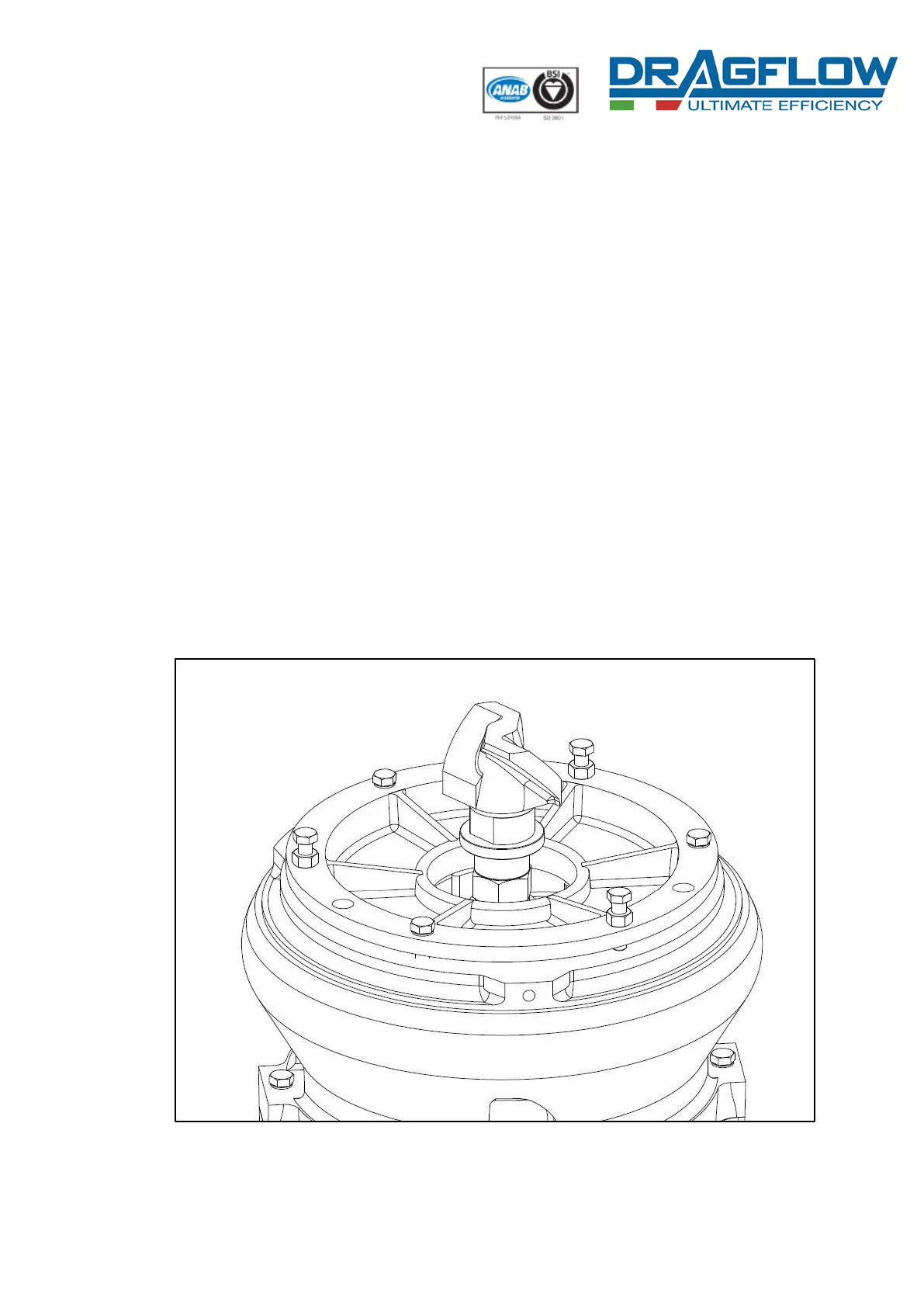
- place the pump vertically and overturned in a stable and safe condition and
remove the strainer (see Strainer section) (Fig. 22);
- loosen completely the n°3 adjusting bolts [206] and make sure that the wear
plate gets in contact with the impeller (see Fig. 23a);
- screw the same n°3 adjusting bolts [206] until 1 mm of clearence between wear
plate and impeller is reached (use 3 feelers positioned at 120° on the inlet hole
diameter between the lower wear plate and the impeller) (see Fig. 23b);
- fix the wear plate position by completely screwing the n°3 nuts [401]
maintaining the adjusting bolts [206] blocked and remove the feelers (see Fig.
24a);
- block the wear plate by completely screwing the n°3 bolts [205] (see Fig. 24a).
Reassemble all the components in reverse order to restore the pump at the initial
conditions. Before reassembling, check the good conditions of any bolt and eventually
replace the damaged ones.
Fig. 22