38 GBK60348: Issue 3
2.7.2.1.3 Recommended Switch Configurations
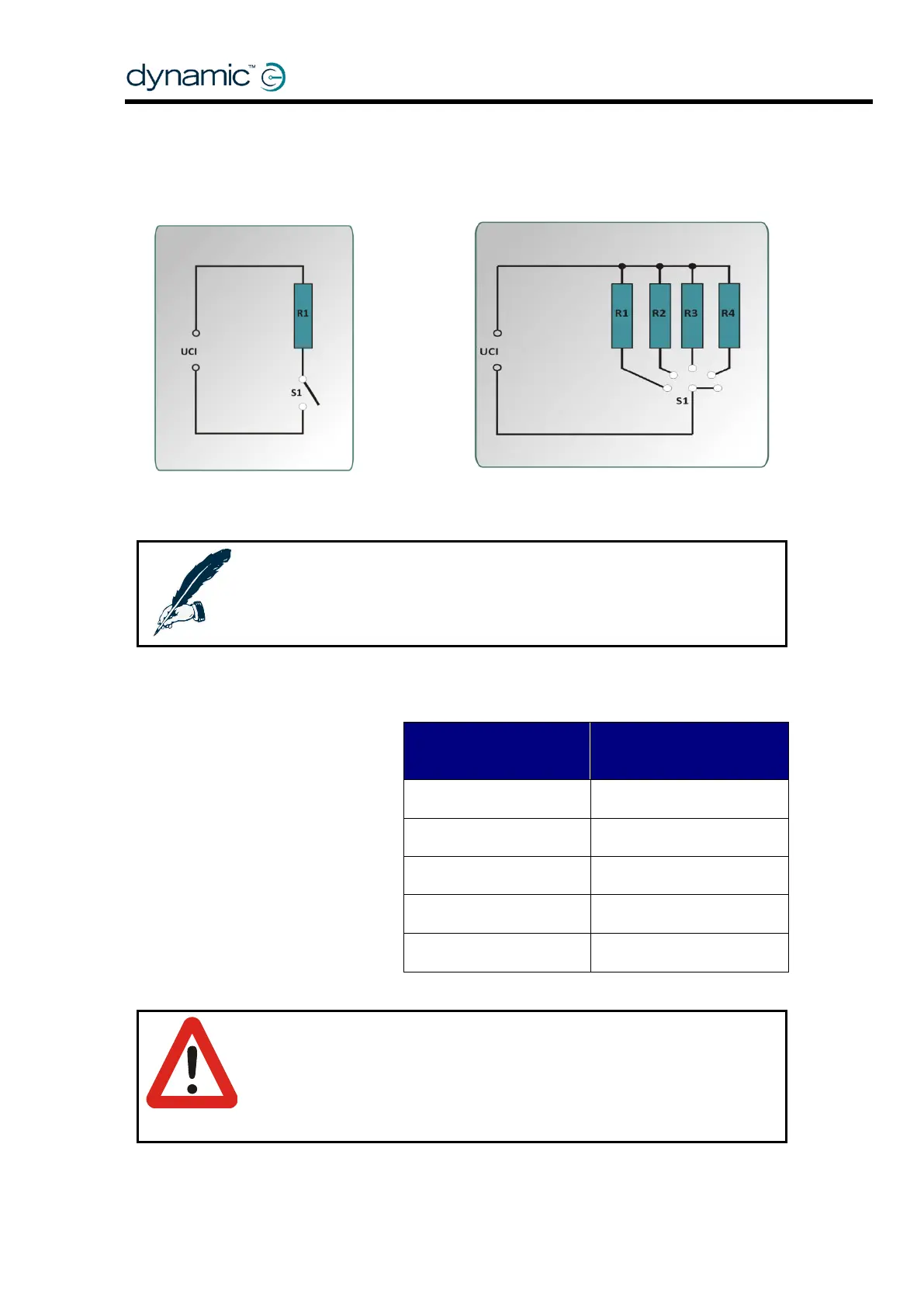
The circuits shown below are example open circuit configurations:
To access a single function
To access multiple functions
Note:
Multiple single switch and resistor combinations can be used in parallel but
the effects of pressing more than one switch at once should be considered.
2.7.2.1.4 Open Circuit Resistance Bands
Warning:
With the open circuit configuration, it is not possible to detect if the switched-
resistor circuit is plugged in to the UCI socket when all the switches are open.
If the application requires that this situation should be detected, then the fail-
safe circuit (see Fail-safe Operation (2.7.2.2)) should be used instead.
The resistances stated in the
‘Nominal resistance across UCI
input’ table, above, are nominal
values only. The actual
resistances should be in the
ranges shown in the following
table.
Acceptable resistance
range (Ω)