CHAPTER 3
DynoWare RT Installation
DynoWare RT Upgrade for Model 424x Dynamometers Installation Guide
3-14
ALIGNING THE SPEED PICKUP CARD
Use the following instructions to align the speed pickup card on the stationary and
4WD dynos for both above ground and in ground installations.
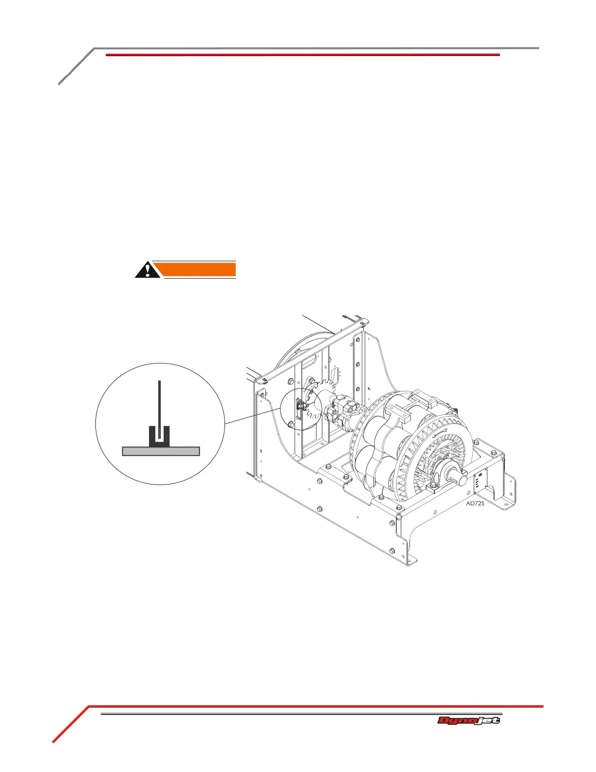
1 While looking through the optical pickup window, note the position of the tab in
the optical pickup. The tab should be centered in the optical pickup and not
contacting it.
2 If the tab is not centered, adjust the tab by loosening the inner bracket mounting
screws and sliding the optical window into position.
3 Be sure to tighten the inner bracket mounting screws once aligned.
4 Attach the black 3-pin connector from the DynoWare RT speed pickup/brake
cable (P/N 76950547) to the speed pickup card on the stationary and 4WD dyno.
The optical pickup is very delicate. Be careful not to damage the optical
pickup.
Figure 3-10: Align the Optical Pickup on the Speed Pickup Card
optical
pickup
tab on
dyno
speed pickup
card
top view of speed pickup card,
optical pickup, and tab on dyno