3-5
MODEL 424 DYNOWARE RT UPGRADE WITH EDDY CURRENT BRAKE
Remove the DynoWare EX Electronics
Version 5 DynoWare RT Upgrade for Model 424x Dynamometers Installation Guide
REMOVE THE DYNOWARE EX ELECTRONICS
Use the following instructions to remove the DynoWare EX electronics and wiring
from both the above ground and in ground dynos.
Note: If your 4WD dyno is equipped with only one eddy current brake, follow the
steps below for the dyno with an eddy current brake. Refer to “Remove the
DynoWare EX Electronics” on page 2-3 for the dyno without an eddy current
brake. Refer to Figure 3-20 on page 3-25 for routing the cables with one eddy
current brake.
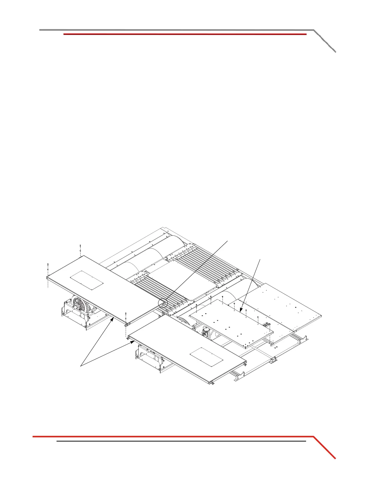
REMOVING THE PIT COVERS—IN GROUND DYNOS
1 Remove the two 3/8-16 x 3-inch bolts and seven 3/8-16 x 1/2-inch button head
bolts securing the left pit cover and set aside.
2 Remove the left pit cover and set aside.
3 Remove the three 3/8 x 1.5-inch bolts and three 3/8-inch flat washers securing
each eddy current brake pit cover feet to the floor and set aside.
4 Remove the 3/8 x 1-inch bolt securing each eddy current brake pit cover to the
support leg and set aside.
5 Remove each pit cover and set aside.
6 Continue with “Removing the Theta Controller—In Ground Dynos” on page 3-7.
Figure 3-1: Remove the Pit Covers
left pit cover
eddy current brake
pit cover
remove bolt securing
cover to support leg