Function of UA 300 D
6
Version 2.03 27. Juni 2008
Two−zone operation
Controller type Required sensors Optional sensors
UA 111 X
UA 111 XP
R2.1 R2.8 R2.2 R2.3 R2.4 R2.5 R2.6 R2.7 R4.1 R4.8
UR 141 R1.1 R1.3 R4.1 R4.3 R1.2 R1.3 R1.4 R4.2 R4.4
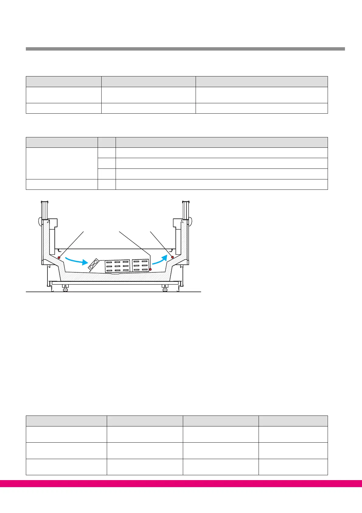
Sensor identification
Legend: Rx.y
x = Sensor type
1 Defrost sensor (evaporator sensor)
2 Supply air sensor
4 Return air sensor / room air sensor
y = Case part 1..8 Case part 1..8
ZNR. 51203 72 930 DEF
R4.y R1.y R2.y
Sensor break alarm
If required sensors are not connected, alarm is always generated in a sensor break. With optional sensors,
alarm is only generated when the sensors are included in sensor scan. Sensor scan can be initiated from a
menu (see Section Menu Structure).
The CI 3000 Store Computer does not archive actual temperature values for optional sensors that are not inclu-
ded in sensor scan.
3.2 Controller function
The sections following describe the various functions of the UA 300 D for control of refrigeration points. Availabi-
lity of certain controller functions depends on the controller type set on DIP switch S3 (see Section 4.3.2 Setting
Controller Type).
The separate controller types are summarized below:
UA 111 X UA 111 XP UR 141
Refrigeration Zone 1 Switches with compressor Majority of supply air sensors
Zone 1
On−off control by room air
sensors Zone 1
Compressor Zone 1 /
Compressor Zone 2
Majority of supply air sensors
Zone 1
Neutral zone pressure switch
(digital inputs)
−−−
Refrigeration Zone 2 On−off control by supply/return
air sensors Zone 2
On−off control by supply/
return air sensors Zone 2
On−off control by room air
sensors Zone 2