Pin and Terminal Assignments of UA 300 D
35
E 2007 − ECKELMANN | BERLINER STRASSE 161 | 65205 WIESBADEN | FON +49(0)611 7103-0 | FAX 49(0)611 7103-133 | eckelmann.de
Version 2.03 27. Juni 2008
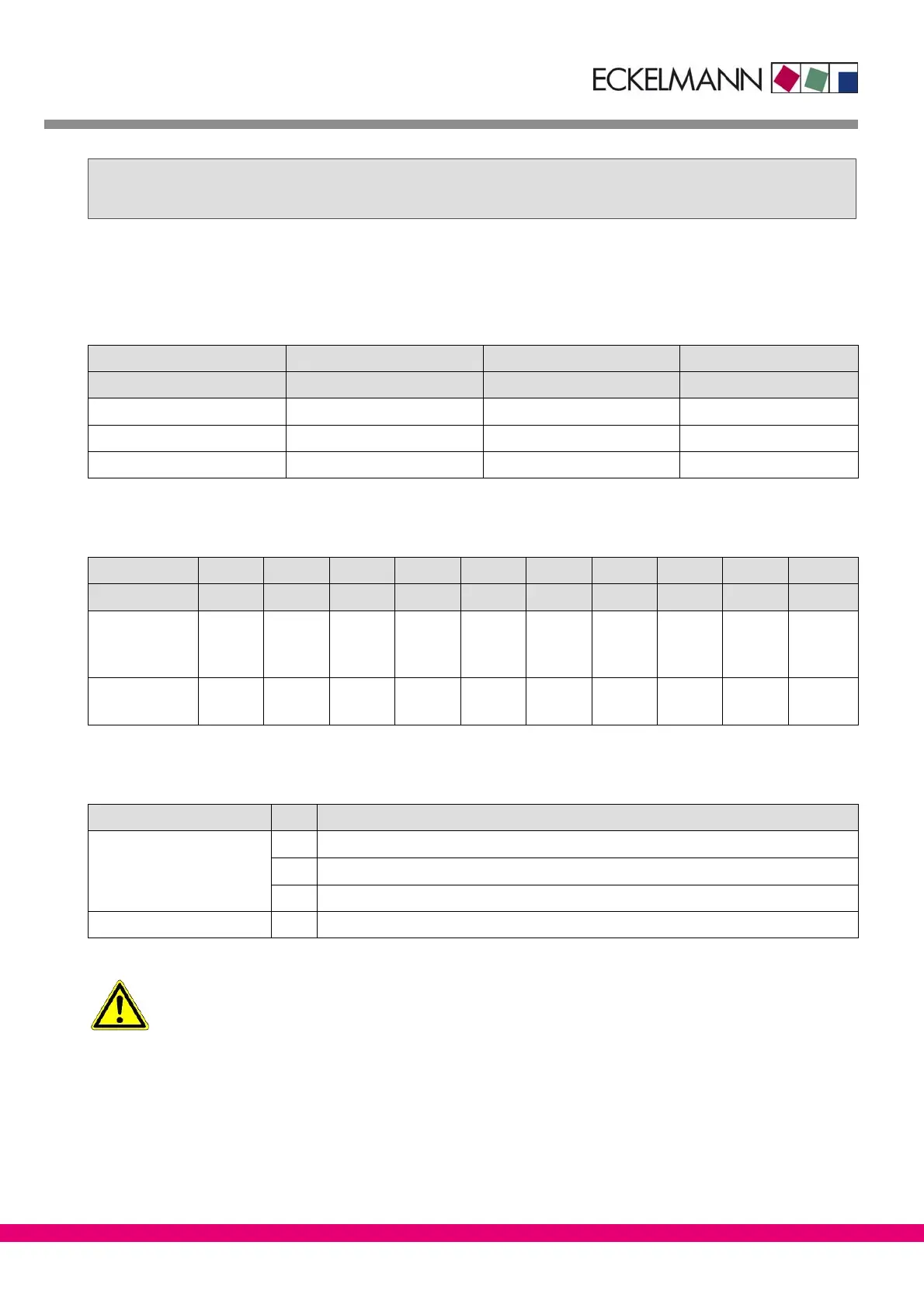
5 Pin and Terminal Assignments of UA 300 D
Digital inputs 230 V AC
Controller type Digital Input 1 Digital Input 2 Digital Input 3
Terminal No. D11/D12 D21/D22 D31/D32
Case controller UA 111 X 2/3 store lighting Setpoint toggle Case lighting switch
Case controller UA 111 XP Load compressor Setpoint toggle Unload compressor
Coldroom controller UR 141 Coldroom door 1 Setpoint toggle Coldroom door 2
Sensors
Controller Type Sensor 1 Sensor 2 Sensor 3 Sensor 4 Sensor 5 Sensor 6 Sensor 7 Sensor 8 Sensor 9 Sensor 10
Terminal No. Z11/Z12 Z21/Z22 Z31/Z32 Z41/Z42 Z51/Z52 Z61/Z62 Z71/Z72 Z81/Z82 Z91/Z92 Z01/Z02
Case
UA 111 X
UA 111 XP
R2.1
R2.1
R4.1
R4.1
R2.2
R2.2
R2.3
R2.3
R2.4
R2.4
R2.5
R2.5
R2.6
R2.6
R2.7
R2.7
R2.8
R2.8
R4.8
R4.8
Coldroom
UR 141 −− R4.1 R1.1 R4.2 R1.2 −− R4.3 R1.3 R4.4 R1.4
Sensor identification
Legend: Rx.y
x = Sensor type
1 Defrost sensor (evaporator sensor)
2 Supply air sensor
4 Return air sensor/room air sensor
y = Case part 1..8 Case part 1..8
All leads running to and from the UA 300 D − especially those of the CAN bus − must be shielded! No
shielding is required on sensor leads when installed exclusively inside the refrigerated display case
and when external interference (for example from parallel power wires) is not to be expected.