Pin and Terminal Assignments of UA 300 D
36
Version 2.03 27. Juni 2008
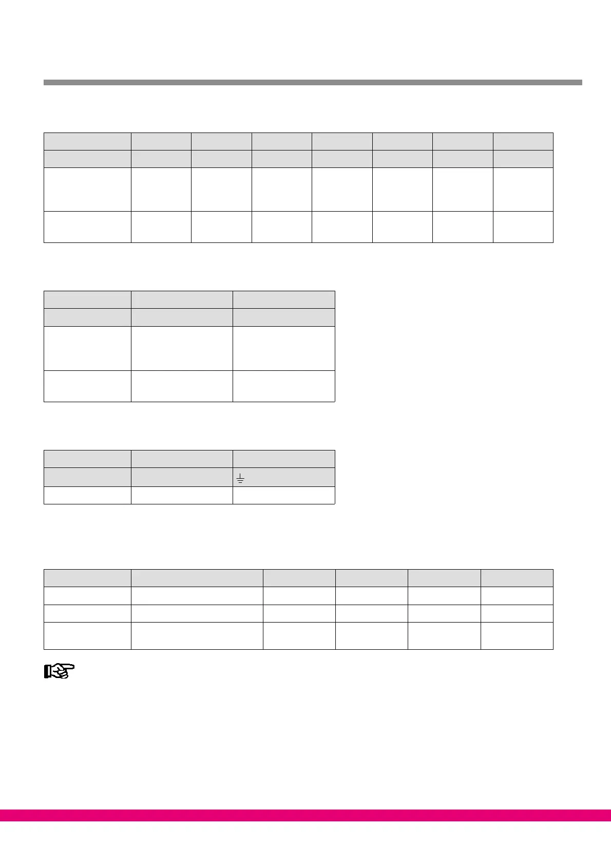
Relay outputs 230 V AC
Controller type Relay 1 Relay 2 Relay 3 Relay 4 Relay 5 Relay 6 Relay 7
Terminal No. 15, 16, 18 25, 26, 28 35, 36, 38 43, 44 53, 54 63, 64 73, 74
Case controller
UA 111 X
UA 111 XP
Alarm
Alarm
Cooling 1
Cooling 1
Cooling 2
Cooling 2
Compressor 1
Compressor 1
Compressor 2
Compressor 2
−−−
Compressor 3
Fan
Fan
Coldroom controller
UR 141 Alarm Cooling 1 Cooling 2 Defrost 1 Defrost 2 Fan 1 Fan 2
Digital outputs 24 V DC
Controller Type Output 1 Output 2
Terminal No. 81, 82, 83 91, 92, 93
Case controller
UA 111 X
UA 111 XP
Case lighting
Not used
Not used
Not used
Coldroom controller
UR 141 Not used Not used
Power supply
Controller Type Power Supply Protective Conductor
Terminal No. N, L
All controllers 230 V AC PE
Relay operation
The following table shows operating direction of the digital outputs for the separate controller types.
Controller type Cooling Defrost Fan Alarm Compressor
UA 111 X Positive −−− Inverted Inverted Positive
UA 111 XP Positive −−− Inverted Inverted Positive
UR 141 Zone 1 (LT): Inverted
Zone 2 (NT): Positive
Positive Positive Inverted −−−
Positive means that operation of the relay is not inverted:
The relay is energized when the controller activates the function output (e.g. Cooling = ON).
(This means that the contact of a normally open relay is closed.)
The relay is not energized when the controller deactivates the function output (e.g. Cooling = OFF).
(This means that the contact of a normally open relay is open.)
Inverted means that operation of the relay is inverted:
The relay is not energized when the controller activates the function output (e.g. Alarm = ON).
(This means that the contact of a normally open relay is open.)
The relay is energized when the controller deactivates the function output (e.g. Alarm = OFF).
(This means that the contact of a normally open relay is closed.)
 Loading...


