Installation and Startup of UA 300 D
26
Version 2.03 27. Juni 2008
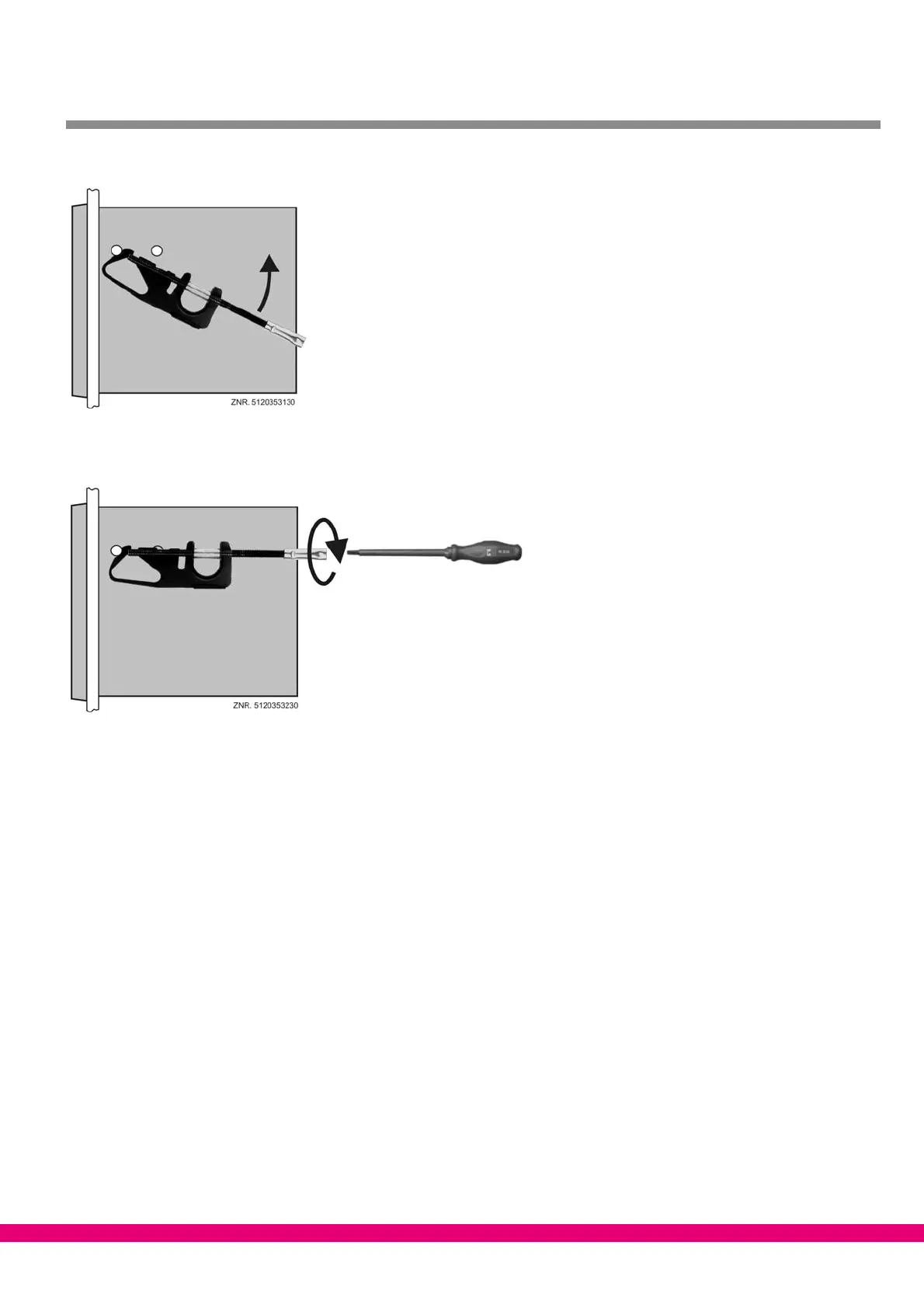
2. Turn fastening brace (5) up on front support pin (3) and press slightly to snap on second support pin (4).
3. Using a screwdriver, tighten fastening screw (6) on control panel. Then make electrical connections on
UA 300 D xS (see Section 5).
After completing installation and electrical connections, parameter settings must be made on the hardware and
in the software of the controller.
4.3 Basic parameter settings
The basic parameter settings are made in the hardware and software at the time the UA 300 D Case Controller
is commissioned:
S Setting of Node No. (Nd.nnn = 1 .. 99) or CAN bus address by decade switches S1 and S2 (UA 300 D CC/CS/
AC/AS only). These switches are not fitted on stand−alone controllers (UA 300 D TC/TS) and an address can-
not be assigned.
S Setting of controller type by DIP switch S3 with Coding Switches 1 .. 3.
S First start (optional setting of default values to obtain a defined starting state for regular operation).
S Setting of basic parameters.