Function of UA 300 D
21
E 2007 − ECKELMANN | BERLINER STRASSE 161 | 65205 WIESBADEN | FON +49(0)611 7103-0 | FAX 49(0)611 7103-133 | eckelmann.de
Version 2.03 27. Juni 2008
3.2.9 Lighting control
Controller type: UA 111 X Version V1.10 and higher only
Actuation of display case lighting can be provided on the UA 111 X. Four lighting states are presumed:
(A) Lighting all off
(B) One third lighting on
(C) Two thirds lighting on
(D) Complete store lighting all on
With lighting all off (A) and one−third lighting on (B), lighting is always switched off in the display case. Lighting in
the display case is always switched on and off when switching from one−third to two−thirds lighting on and back.
The display case lighting can be switched manually in any of states (B), (C) or (D), every actuation of the light
switch causing the case lighting to be switched either ON or OFF. For this function Digital Input 1 (terminals
D11/D12) is provided on the UA 111 X for two−thirds lighting on and Digital Input 3 (terminals D31/D32) is provi-
ded for the lighting switch.
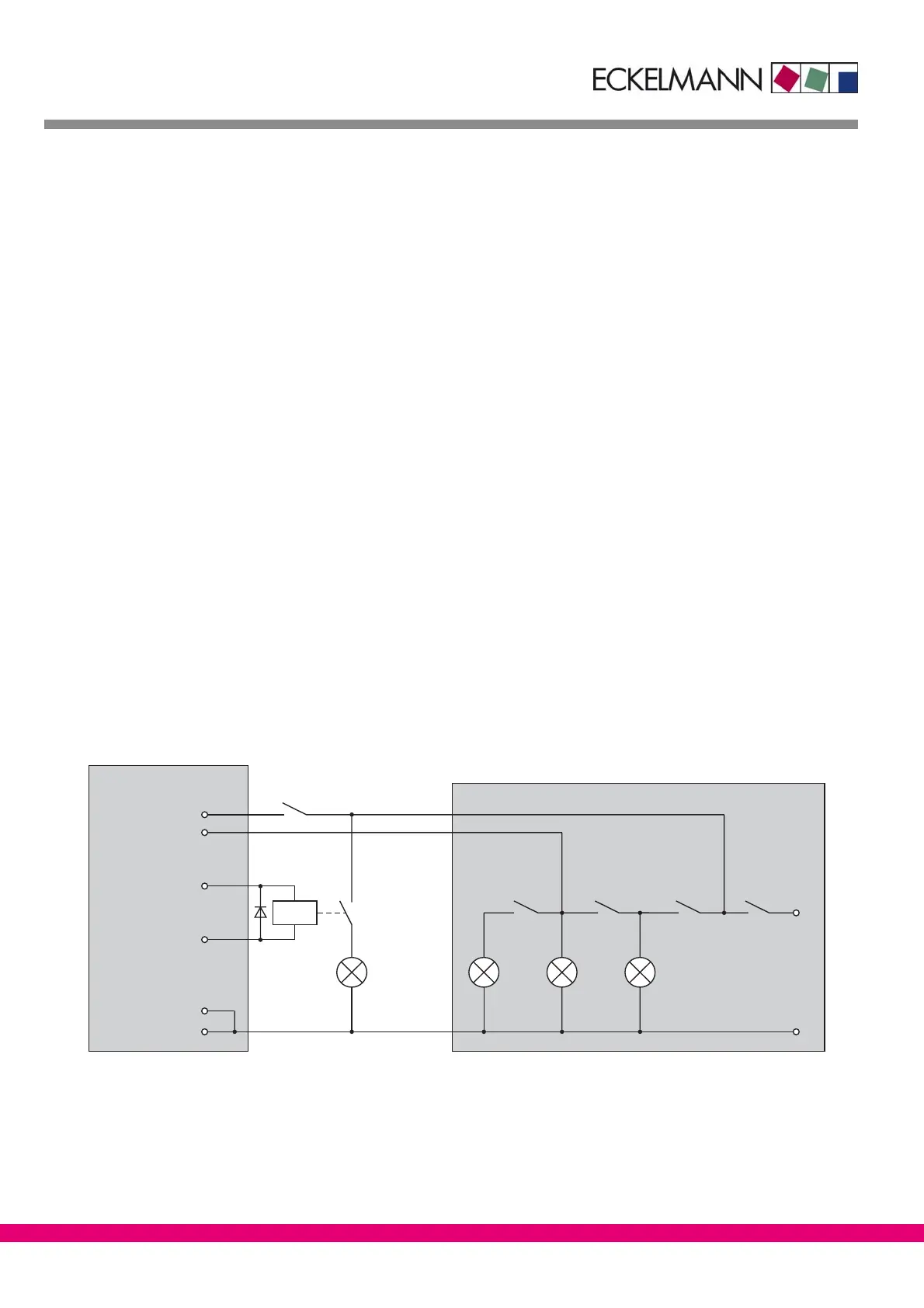
The case lighting is operated by the 24 V digital output (terminals 81/82). Make sure that this output is connec-
ted to a freewheeling diode as shown in the following picture.
Wiring note:
State (A) must be invoked by means external to the controller. Power is then cut off from the lighting in the dis-
play case (but not from the controller itself!). Lighting in the store and outside the display case is likewise not
controlled by the controller.
In states (B) and (C) external power is continuously supplied to the display case but routed through a relay ope-
rated by the digital output (terminals 81/82). The controller then switches the lighting as a function of the digital
inputs. (D) is likewise a state that must be controlled by means external to the controller.
For the controller there is no difference between state (A) and (B) (Digital Input 1 being de−energized). State (C)
and (D) is also not seen as different by the controller (Digital Input 1 is energized). The following diagram illu-
strates the basic wiring for lighting control:
81
(+24V)
(D) (C) (B)
(A)
CASE
LIGHTING SWITCH
3/3 2/3 1/3
CABINET
LIGHTING
82
(OUT)
UA 111 X
D11
D32
D12
D31
MARKET LIGHTING (EXTERNAL)
ZNR. 51203 69 630 E1
L1
N
24VDC
DIGITAL INPUT 1
DIGITAL INPUT 3
DIGITAL OUTPUT
DIGITAL INPUT 1
DIGITAL INPUT 3