Function of UA 300 D
11
E 2007 − ECKELMANN | BERLINER STRASSE 161 | 65205 WIESBADEN | FON +49(0)611 7103-0 | FAX 49(0)611 7103-133 | eckelmann.de
Version 2.03 27. Juni 2008
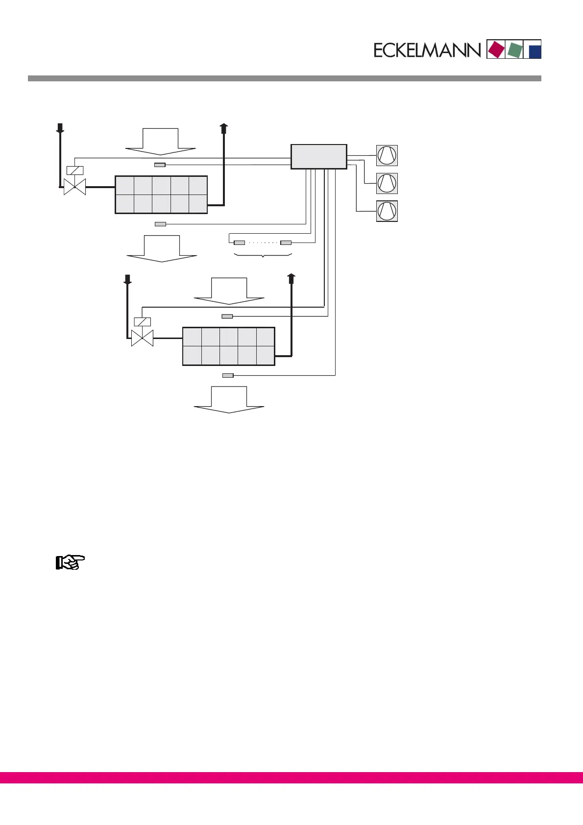
Two−zone operation:
Valve 1
Return
air
R4.1
R2.1
Return
air
Valve 2
R4.8
R2.8
Supply
air
Supply
air
Verdampfer 1
Evaporator 1
Verdampfer 2
Evaporator 8
Refrigeration point
controller
UA 300 D
ZNR. 51203 72 130 E1
R2.2 R2.7
(optionally)
Compressor 1
Compressor 2
Compressor 3
only UA 111 XP /
optionally
R2.1 .. R2.7: Supply air sensor (Terminal Z11/12; Terminal Z31/32 .. Terminal Z81/82)
R4.1: Return air sensor (Terminal Z21/22)
R2.8: Supply air sensor (Terminal Z91/92)
R4.8: Return air sensor (Terminal Z01/02)
Valve 1: Solenoid Valve 1 relay (Terminal 25/26/28)
Valve 2: Solenoid Valve 2 relay (Terminal 35/36/38)
Compressor 1 relay (Terminal 43/44)
Compressor 2 relay (Terminal 53/54)
Compressor 3 relay (Terminal 63/64 − UA 111 XP ONLY)
When connecting the supply air sensors, make sure there are no free locations between the connec-
ted sensors. For example, when connecting four supply air sensors, the consecutive inputs R2.1 to
R2.4 must be used.
 Loading...


