Step 4: Connect the positive battery cable (Red) to the positive battery terminal (BAT+) and the
negative battery cable (Black) to the negative battery terminal (BAT-) with a torque rating of ≈97 - 106
in-lbs. (11 – 12 Nm) per connection.
Step 5: Be sure not to cross-polarize, as this will damage the equipment.
The recommended battery cable and terminal size are as follows:
*Charging Current: 115A @48VDC (AC), 125A @48VDC (PV)
*Discharging Current: 140A
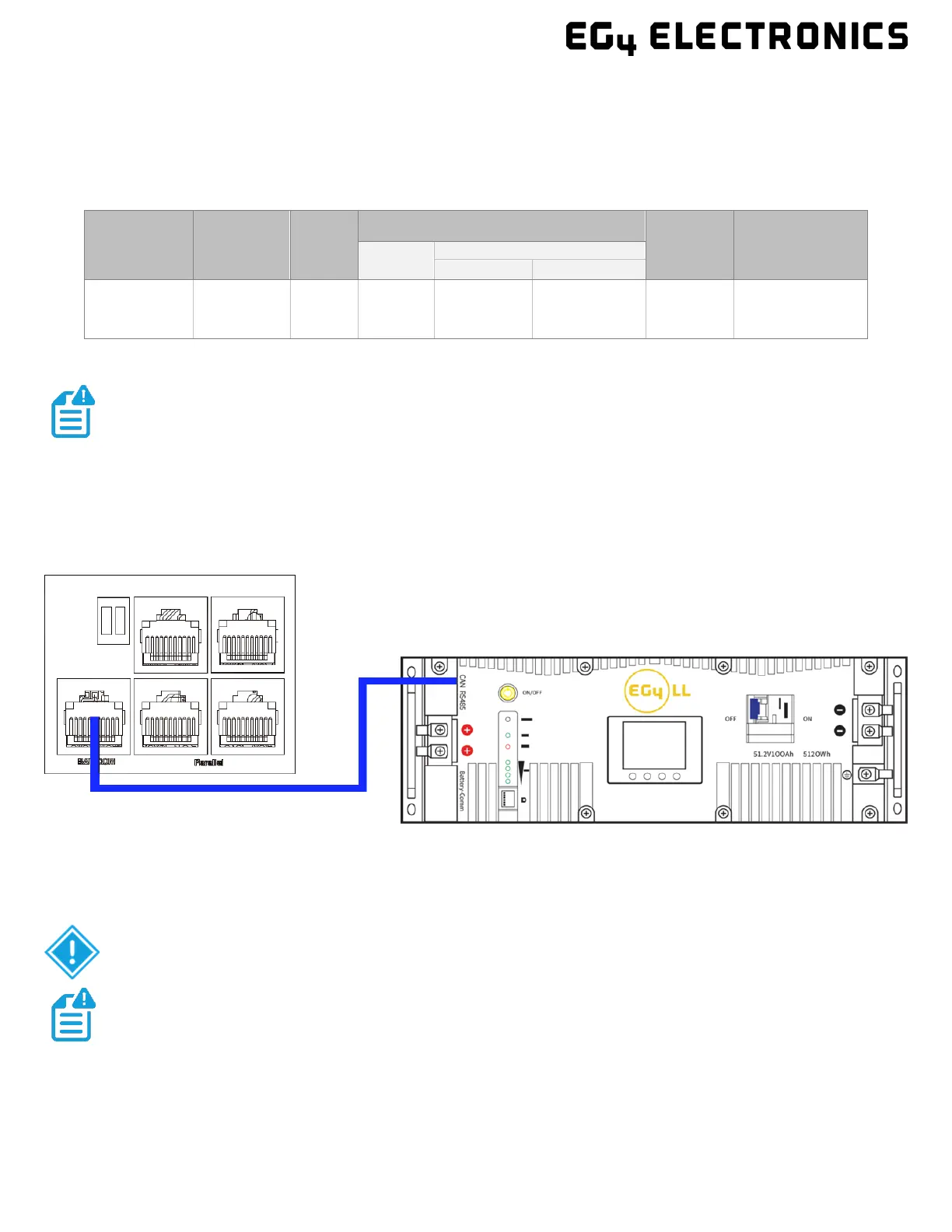
5.6.2 LITHIUM BATTERY COMMUNICATIONS
Upon successful installation of the batteries, follow the next steps to enable closed-loop
communications (with compatible battery modules) between batteries and inverter.
1. Connect either the CAN or RS485 (depending on make/model of battery) communications cable
between inverter and battery. See diagram below.
2. For the inverter to communicate with the battery BMS, setting 3 must be changed to “Li-io n”.
The inverter will then switch to a secondary setting. Here, select the make/model of battery
and press enter to registers the change. For EG4 batteries, select “0” after confirming “Li-ion”
as the battery type.
Maximum
Amperage
Battery
Capacity
Wire
Size
Ring Terminal
To rq u e
Value
Ter min a l
Temperature
Rating
Cable
(mm
2
)
Depth
Length
140A* ≥200AH 1 AWG 38
.25 in.
(6.4mm)
1.5 in.
(39.2mm)
97 – 106 in-
lbs.
(11 – 12 Nm)
-40 - +248°F
(-40° - +120°C)
NOTE: The recommended battery capacity of one 6000XP inverter is ≥200AH
ATTENTION: If attempting to BMS communicate with EG4 LifePower4 batteries,
an optional firmware update will need to be performed on the batteries.
If needing to extend the inverter to battery communication cable, or to
build a new one, please refer to the following table for the inverter pinout