16
For battery specific pinouts, please refer to the respective battery user manual.
5.7 AC WIRING INFORMATION
When sizing AC wires, please adhere to the following information.
AC Cable Requirements:
Terminal Connection
Wire Size
Torque Values
GRID
8 AWG (10mm
2
) 18 in-lbs. (2 Nm)
GEN
8 AWG (10mm
2
) 18 in-lbs. (2 Nm)
LOAD
8 AWG (10mm
2
) 18 in-lbs. (2 Nm)
Ground-Neutral Bonding
The information below describes the nature of the ground and neutral in the inverter and
their relationship to the system. Always consult with the installer or a licensed electrician
to ensure that the right configuration is being used:
• The neutral line is a solid connection between AC input and AC output (known as
a Common Neutral Architecture).
• The neutral line between the AC input and AC output is never disconnected.
• This architecture assumes there is a single neutral-ground bond in the system. Typically, the
neutral-ground bond for a system will be at the first means of disconnect for the grid. However, if
there is no neutral-ground bond in the system, the 6000XP can be configured to create the bond
internally (see setting 26).
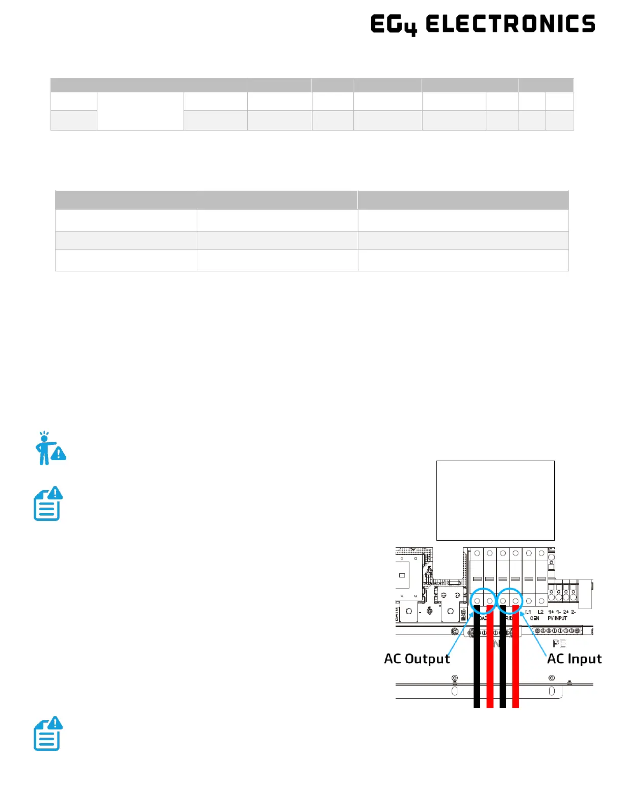
5.7.1 STEPS FOR AC CONNECTION
Please follow the steps outlined below to ensure proper
AC Input/Output connections.
Step 1: Before installation of any wiring, please ensure all
breakers are open (o) before making any connections. Use a
multimeter to confirm the AC Input lines (L1, L2 and neutral) are
not energized.
Step 2: Strip o 5/16-3/8 in. (8-10 mm) insulation from the AC
cables.
Step 3: Fasten the AC Input wires into their respective terminals
using the proper torque ratings.
CAN
Pin
Description
X X X BMS_CAN H BMS_CAN L X X X
RS485
BMS_485 B BMS_485 A X X X
L1 – Black
L2 – Red
Neutral – White
WARNING: This is not a dynamic bond. It is either always enabled or always disabled.
NOTE: Always be sure to connect the AC Output ground
wire to the Ground terminal bus (labeled PE in the diagram)
first before installing AC Outputs L1 and L2.
After connecting all AC wiring, put the built-in LOAD breaker back to the ON
position before providing power to the load.
If using fine stranded wire, use ferrules to secure the connections to the inverter.