18
5.8.3 GENERATOR AC CONNECTIONS
Please follow the steps listed below to ensure the generator connections are properly installed.
Step 1: Before making any wiring connections, be
sure to have the inverter(s) powered o, the
generator powered o, and all circuit breakers
open (o) to prevent damage to the unit.
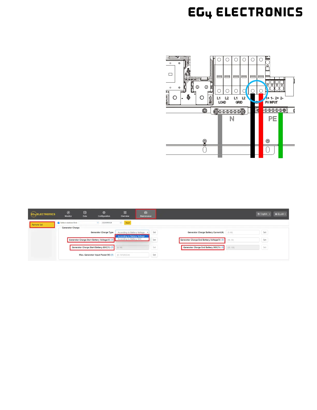
Step 2: Properly identify the generator’s output
lines. By US wiring standards, L1 wire will be black,
L2 will be red, Neutral will be white, and ground will
be green. Once identified, remove ≈3/8 in. (≈10mm)
from the insulation sleeve on the wires.
Step 3: Ground the generator’s output ground to
the Ground Bus (labelled PE) of the inverter.
Step 4: Install L1 to the GEN port’s L1 terminal, then
install L2 to the GEN port’s L2 terminal. Next,
fasten the Neutral wire from the generator into the
N-BUS (Neutral Bus).
5.9 GENERATOR START AND STOP SETTINGS
Using the EG4 Monitoring Software, go to the “Maintenance” page where “Remote Set” will
be selected automatically. Scroll to the “Generator Charge”’ section and select the
“Generator Charge Type” (see screenshot below). Normally, lead-acid batteries are charged
according to voltage and Lithium batteries are charged according to SOC.