103
Appendix
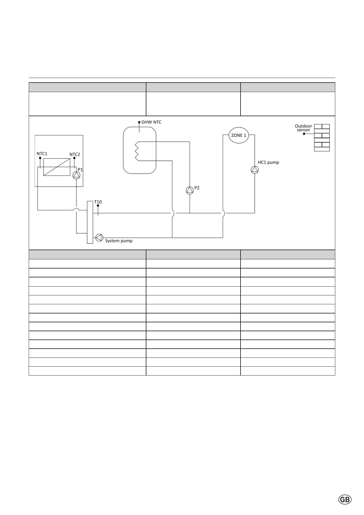
Standard schemes
Scheme Boiler group Distribution group
4
Singleboilerorcascade
• DHW tank downstream
hydraulic separator
• From 1 to 3 mixing zone
Name and Description ECU I/O Note
Outdoor sensor NTC4
Boiler pump (230 V) P1
Boiler pump (PWM)
PWM_P1
Boilerowsensor NTC1
Boiler return sensor NTC2
DHW tank sensor NTC3
DHW pump P2
T10 MTS1
HC1 pump VFR1 See note *1
System pump* MO1_HV
Heat request zone 1 PADIN1 or EBUS2
Alarm or sanitary pump VFR1 Optional;seenote*1
LPG/ Room supply Fan VFR3 Optional
Note:
1. IfalltheVFRareneededforotherfunctions(alarm,uegasdumper,LPG,…),
HC1pumpmustbeconnectedtoP_Z1ofControlledwithCLIP3ZONEMIX.CLIP3ZONEMIXisneeded!
*System pump: optional electrical connection. To use depending on application.