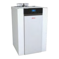
Individual flue:
min. 500mm
Collective flue:
dependant on
the selected
flue system.
the supplier
50 - 70 mm
18
Installation
Installation Connections
The installation location of the
CH-boiler(s)hastobe,andremain,
frost-free.
It is NOT necessary to have a purpose
provided air vent providing a twin
pipeorconcentricroomsealedue
system is used in the room or internal
spaceinwhichtheboilerisinstalled.
Neither is normally required a provision
for general cooling due to the very
lowheatlossfromtheboilerheat
exchanger and casing.
Theoorshouldbeatandleveland
havesucientdeadweightcapacity
forthecomplete(lled)installation.
Wheelscanbeadjusted+/-10mmto
compensateeventualoorirregularity.
The ELCO TRIGON L PLUS cascade
canbemountedin2ways:
- Floor standing in line
Allboilersstandingalongsideone
100 mm
1000 mm
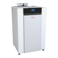
1. Boiler return connection
2. Boilerowconnection
3. Condensate drain
4. Gas
5. Flue gas outlet
6. Air supply
anotherinaoorstandingframe.
Refer to page 21.
- Floor standing back-to-back.
Allboilersstandingback-to-back
onaoorstandingframe.
Refer to page 22.
General guidelines:
Pay attention to the minimum
distance required between the
boilers, walls and ceiling for
installing and removing the housing
(refer to above) for commissioning
and servicing and installing the ue
system (refer to chapter 7).
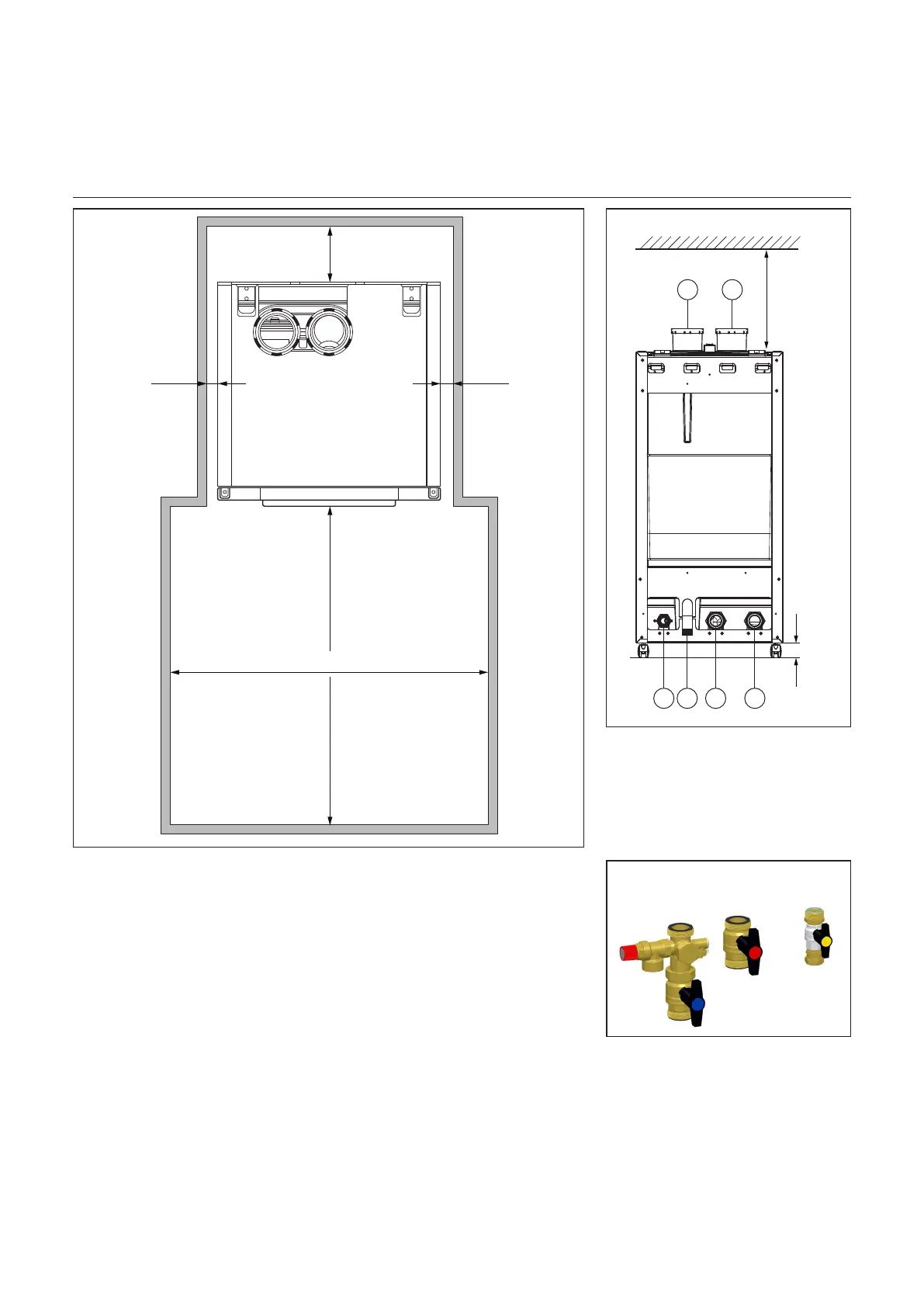
Ifyouhaveoptedtobuildthehydraulic
part yourself, then ELCO recommends
using “Connection set TRIGON L PLUS
assingleboiler”foreachboiler.
1234
5 6