32
Flue gas connection
WerecommendtheuseofELCO’s
comprehensiverangeofuegas
components.
For further information, please see the
installation instructions:
- ELCO wall terminals
- ELCO roof terminals
- ELCOuepipecomponents,both
individualpipesandconcentrictubes.
Regulationsabouttheconstruction
andinstallationofuegassystems
aredierentfromcountrytocountry.
Itmustbeensuredthatallnational
regulations with regard to chimney
systemsareobserved.
Notes
Thetablesbelowgiveguidanceon
themaximumlengthsofairandue
gastubesthatmaybeconnected.Ifa
roomsealedinstallationisbeingmade
utilisingseparateairandue
gastubes,thelengthsofbothtubes
mustbeaddedtogetherandnot
exceed the relevant value given in the
tables.
Theradiusofanybendusedintheue
gassystemmustnotexceed87.5°.
Walls that are sensitive to heat
should be insulated.
Construct the ue system in such
way that no recirculation may take
place.
Installation
Connections
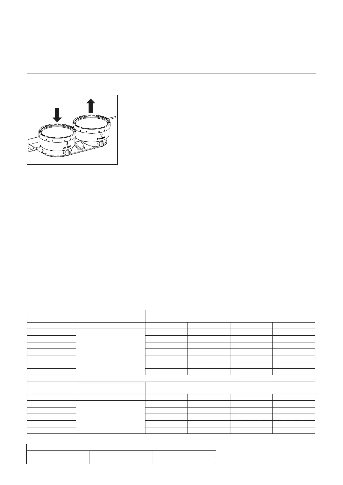
Air- / ue gas ducts for individual boilers
Allboilermodelshaveaparallelue
connection.
It is not necessary to install a separate
condensatedrainfortheuegas
system,sincethecondensatewillbe
ushedoutviatheboilerandintothe
siphon.Pleaseobservethefollowing
recommendations:
- Only use corrosion-resistant
material
- Thediametermustbecalculated
and selected according to the
national regulations.
- Thelengthoftheuegassystem
mustbekeptasshortaspossible
(and must not exceed the
maximum permitted length, see the
documentation for planners)
- Horizontaluegastubesmusthave
aninclinationofatleast3°back
towardstheboiler.
Air supply connection
If required, a separate room sealed
airsupplytubemaybeconnected
via the inclusion of the optional air
supplyconnectortting.Thediameter
mustbecalculatedinconformitywith
nationalregulationsandincombination
withtheuegasgassystem.The
overall resistance of the air supply
anduegastubesmaynotexceed
the maximum supply pressure of the
Fan at any time. (Also see the Chapter
“Technical data”)
Dimensioning (reference value)
Required minimum (ue enclosure) shaft cross-section
Diameterueduct Square shafts Round shafts
100 mm 140 x 140 mm 160 mm
Øtubes(openorparalleltubes
room sealed installation)
Maximum length in metres
Changes of direction 0 2 3 4
60
Ø100 mm
82 78 76 74
70 60 56 54 52
100 34 30 28 26
120 20 16 14 12
140 16 12 10 8
170
Ø130 mm
35 30 27 25
200 30 25 22 20
Øtubes(concentricroomsealed
installations)
Maximum length in metres
Changes of direction 0 2 3 4
60
Ø100/150 mm
34 30 28 26
70 23 19 17 15
100 13 9 7 5
120 10 6 4 2
140 8 5 3 1