33
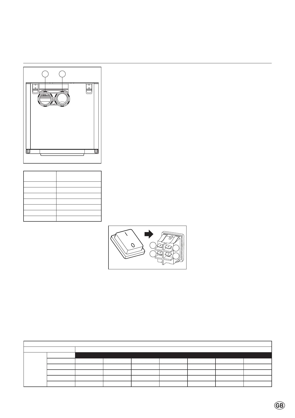
Parallel boiler connection
Theboilercomesasstandardwitha
parallelconnectionfortheuegas
outlet and air supply system.
For the air supply opening (1) diameter
andtheuegasoutletconnection(2),
seetablebelow.
Theairsupplychannelcanbe
connected to it, or, if it involves an
“open device” (Drainage category B),
anairlterisrecommended.
Concentric boiler connection
Theboilers60-70-100-120-140canbe
converted into a concentric connection
using the parallel/concentric adapter
100/150 (optional) and carrying out the
following tasks:
- Open and remove the frontal
panel and the top panel (follow the
instruction on page 42.
- Lift the parallel connection.
- Disconnect the main switch 230V
connection and remove it.
- Replace the parallel connection
with parallel concentric adapter.
- Connectandtthemainswitch
230V according to previous
conguration.
The air supply opening has a diameter
of ø150mm.
Theuegasoutletconnectionhasa
diameter of ø100mm.
Theuegasoutlet-/airsupplysystem
is then connected to the concentric
connection component.
Installation
Connections
Air- / ue gas ducts for individual boilers
TheTRIGONLPLUS-boilerscanbe
usedbothinan“open”andin“closed”
system.
Open system
Therequiredcombustionairistaken
from the immediate environment
(boilerroom).Forthispurpose,please
complywiththeapplicableboilerroom
ventilation regulations.
WhenusingboilercategoryB23and
B33asan‘openboiler’,theprotection
degreeoftheboilerwillbeIPX0D
instead of IPX4D.
Anairlteroragridisrecommended
ontheairintakeoftheboiler(available
as an accessory on pages 15-17.
Closed system
Therequiredcombustionairissucked
in from the outside through a channel.
Thisimprovesinstallationpossibilities
withinabuilding.Ingeneral,outsideair
iscleanerthanairfromtheboilerroom.
When the boiler is op erational,
it produces a white plume of
condensation. This condensation
plume is harmless but may cause
some inconvenience, particularly
in the case of wall terminal. As a
result, roof terminals are preferred.
In a closed installation, roof
terminals should be at the same
height preventing ue gas from
being sucked in by the other boiler
(recirculation). Outlets in recesses
and near erected walls may also
bring about ue gas recirculation.
Recirculation has to be prevented at
all times.
For installation in UK please refer to
installation guidance in BS6644 and
IGE UP10.
Boiler type Air duct - ue gas
diameter
60 100 - 100
70 100 - 100
100 100 - 100
120 100 - 100
140 100 - 100
170 130 - 130
200 130 - 130
21
2
4
1
3
Fan settings correction
By setting parameter (21-2-4) it is
possibletocompensateforahigher
uegaspressuredierence.Itis
required to have a pressure drop
calculationoftheapplieduegas
system.
According the calculated pressure
drop, the correct value for parameter
(21-2-4)hastobechosenfromthe
tablebelow.
For setting parameters see the
applicablechapter.
Flue Gas System pressure drop
Boiler type
Parameter
(21-2-4)
60 70 100 120 140 170 200
0 - 600 161 156 243 143 200 215 265
700 189 204 295 177 230 280 321
800 226 224 350 207 275 313 370
900 250 250 405 240 300 375 -
1000 278 278 457 260 304 375 -